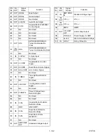


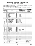


2-4-5
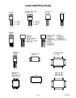
U25NDA
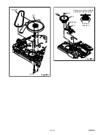
Pin of [12]
Pin of [10]
Grooves of [28]
[28]
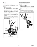
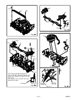
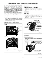
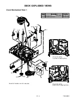
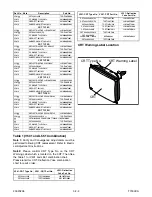
When reassembling [10] and
[12], confirm that pin of [10]
and pin of [12] are in the
grooves of [28] as shown.
[11]
[13]
[12]
A
[10]
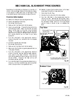
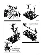
(L-1)
(P-3)
Adj. Screw
(P-2)
(L-2)
View for A
Fig. DM8
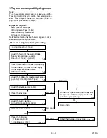
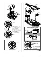
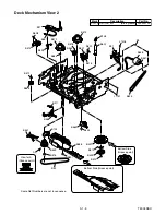
[14]
[15]
(S-9)
(S-8)
Fig. DM9
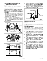
[17]
[16]
[18]
(S-10)
(L-3)
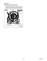
After removing the Screw (S-10),
while pressing the Locking Tab
(L-3), remove [16].
Fig. DM10
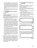
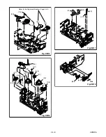
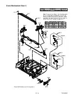
[8]
[8]
[9]
(S-7)
(S-6)
LDG
Belt
A
View for A
Fig. DM7
Desolder
from bottom
Lead with White Stripe
Summary of Contents for 6319CC
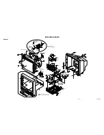
Page 18: ...1 6 2 T7300DC Fig 1 ANT S 1 S 1 1 REAR CABINET S 1 S 1 S 1 S 1 Fig 2 ...
Page 20: ...1 6 4 T7300DC Fig 4 S 5 S 5 S 5 S 5 5 CRT CRT CBA ANODE CAP ...
Page 75: ...Packing X 1 S 1 S 4 S 3 S 3 S 2 TAPE TAPE X 4 X 3 X 2 X 7 S 6 S 14 FRONT 3 1 3 T7300PEX ...
Page 92: ...Printed in Japan 2002 02 20 HO SC319C 6319CC EWC1902 T7300UA 2UC 3UD ...


