


1-7-5
T7300EA
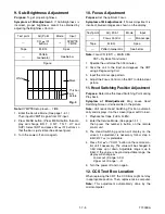
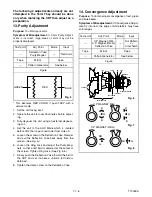
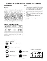
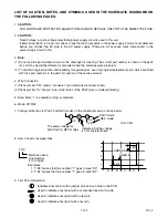
9. Sub-Brightness Adjustment
Purpose:
To get proper brightness.
Symptom of Misadjustment:
If Sub-Brightness is
incorrect, proper brightness cannot be obtained by
adjusting the Brightness Control.
Note:
SYMPTE Setup level --- 7 IRE
1. Enter the Service Mode. (See page 1-4-1.)
Then input SYMPTE signal from RF input.
2. Press MENU button. (Press MENU button then dis-
play will change B R T, C N T, T N T, V-T and
SHP). Select BRT and press CH
o
/
p
buttons so
that the bar is just visible (See above figure).
3. Turn the power off and on again.
10. Focus Adjustment
Purpose:
Set the optimum Focus.
Symptom of Misadjustment:
If Focus Adjustment is
incorrect, blurred images are shown on the display.
Note:
Focus VR (FBT) --- MAIN CBA
FBT= Fly Back Transformer
1. Operate the unit more than 30 minutes.
2. Face the unit to the East and degauss the CRT
using a Degaussing Coil.
3. Input the monoscope pattern.
4. Adjust the Focus Control on the FBT to obtain clear
picture.
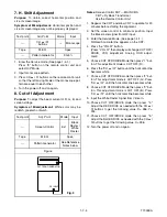
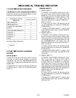
11. Head Switching Position Adjustment
Purpose:
Determine the Head Switching Point during
Play back.
Symptom of Misadjustment:
May cause Head
Switching Noise or Vertical Jitter in the picture.
Note:
Unit reads Head Switching Position automati-
cally and displays it on the screen (Upper Left Corner).
1. Playback test tape (FL8A, FL8N).
2. Enter the Service Mode. (See page 1-4-1.)
Then press the number 5 button on the remote
control unit.
3. The Head Switching position will display on the
screen; if adjustment is necessary follow step 4.
6.5H(412.7
µ
s) is preferable.
4. Press "CH
o
" or "CH
p
" button on the remote con-
trol unit if necessary. The value will be changed in
0.5H steps up or down. Adjustable range is up to
9.5H. If the value is beyond adjustable range, the
display will change as:
Lower out of range: 0.0H
Upper out of range: -.-H
5. Turn the power off and on again.
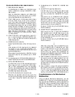
12. CCS Text Box Location
When replacing the CRT, the CCS Box might not stay
in appropriate position. Then, replace micro computer.
Note:
This adjustment automatically done by the
microcomputer.
Test point
Adj. Point
Mode
Input
---
CH
o
/
p
buttons
---
SYMPTE
7.5IRE
Tape
M. EQ.
Spec.
---
Pattern
Generator
See below
Figure
Black
White
This bar
just
visible
Fig. 4
Test point
Adj. Point
Mode
Input
---
Focus Control
---
Monoscope
Tape
M. EQ.
Spec.
---
Pattern Generator
See below.
Summary of Contents for 6319CC
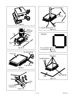
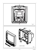
Page 18: ...1 6 2 T7300DC Fig 1 ANT S 1 S 1 1 REAR CABINET S 1 S 1 S 1 S 1 Fig 2 ...
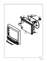
Page 20: ...1 6 4 T7300DC Fig 4 S 5 S 5 S 5 S 5 5 CRT CRT CBA ANODE CAP ...
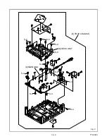
Page 75: ...Packing X 1 S 1 S 4 S 3 S 3 S 2 TAPE TAPE X 4 X 3 X 2 X 7 S 6 S 14 FRONT 3 1 3 T7300PEX ...
Page 92: ...Printed in Japan 2002 02 20 HO SC319C 6319CC EWC1902 T7300UA 2UC 3UD ...


