Procedure
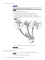
1. Gently insert the new power/cooling module into the enclosure, being sure the
module is completely seated.
2. Secure the module with the captive screw.
Figure 21 Installing a power/cooling module (AC module shown)
CL4569
Removing an LCC
Refer to
while performing the procedure that follows.
Procedure
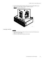
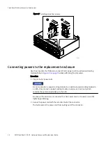
1. Attach an ESD wristband to your wrist and the enclosure in which you are replacing
the LCC.
2. Turn the captive screws counterclockwise to release the LCC.
3. Remove the LCC from its slot and place it on a clean, static-free surface.
CloudBoost Disk Array Expansion Replacement
Removing an LCC
45
Summary of Contents for CloudBoost 100
Page 1: ...EMC CloudBoost 100 Version 2 0 Hardware Component Replacement Guide P N 302 002 471 REV 02 ...
Page 6: ...FIGURES 6 EMC CloudBoost 100 2 0 Hardware Component Replacement Guide ...
Page 8: ...TABLES 8 EMC CloudBoost 100 2 0 Hardware Component Replacement Guide ...
Page 14: ...CloudBoost 100 Overview 14 EMC CloudBoost 100 2 0 Hardware Component Replacement Guide ...
Page 20: ...Disk Drive Replacement 20 EMC CloudBoost 100 2 0 Hardware Component Replacement Guide ...


