


19
IND100133-34
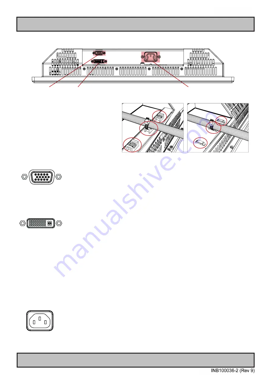
RGB IN
AC Power Input
Connection area of display (illustration)
Cable Tension
To reduce tension on the cables you connect,
secure them with a cable tie to the base
mounted clamp or to the chassis hinges.
For certain models a base mounted clamp
is available (FIG 1). For other models a hinge
in the chassis is available (FIG 2).
FIG 1
FIG 2
Physical Connections - STD Based Models
DVI-I IN
RGB IN:
Connect the VGA cable to the D-SUB 15P Connector (female). Secure the VGA cable to the hex spacers provided on
the unit and make sure you do not bend any of the pins inside the connector when connecting. Connect the other end
of the cable to the VGA connector on your equipment and secure it.
DVI-I IN:
Connect your DVI cable to the DVI-I 29P Connector (female). The DVI-I connector can function as regular RGB IN by
using a DVI-I > RGB/VGA adapter. Secure the DVI cable to the hex spacers provided on the unit and make sure you
do not bend any of the pins inside the connector. Connect the other end of the cable to the DVI connector on your
equipment and secure it.
Important note for DVI signal detection:
Please note that for the operating system to detect DVI signals correctly, the DVI cable MUST be connected physically
to the display unit during boot up otherwise you may experience a black image. Furthermore certain graphics drivers
may need to refresh their device list (often done manually by user - detect devices), while in some cases the
Plug-n-Play will automatically detect the DVI signal correctly. Please consult your local technician if you have this
behavior of detection problems when using DVI. In all cases the problem can be solved in the operating system, and
this is not a malfunction in the graphic controller for HATTELAND® units.
POWER INPUT:
(For models supporting AC input)
The internal AC power module supports both 115VAC/60Hz and 230VAC/50Hz power input.
Summary of Contents for Hatteland Technology Series 1
Page 6: ...6 This page left intentionally blank...
Page 7: ...7 General...
Page 13: ...13 Installation...
Page 20: ...20 This page left intentionally blank...
Page 21: ...21 Operation...
Page 38: ...38 This page left intentionally blank...
Page 39: ...39 Specifications...
Page 41: ...41 Technical Drawings...
Page 43: ...43 Technical Drawings Accessories...
Page 51: ...51 Appendixes...
Page 60: ...60 Appendix IND100077 24 User Notes...
Page 62: ...Hatteland Technology AS www hattelandtechnology com Enterprise no NO974533146...


