


89
Appx. C
20
SA11
SYSCLK
—
—
21
SA10
IRQ7
—
—
22
SA9
IRQ6
—
—
23
SA8
IRQ5
—
—
24
SA7
IRQ4
—
—
25
SA6
IRQ3
—
—
26
SA5
DACK2*
—
—
27
SA4
TC
—
—
28
SA3
BALE
—
—
29
SA2
+5 V
—
—
30
SA1
OSC
—
—
31
SA0
0 V
—
—
32
0 V
0 V
—
—
* active low
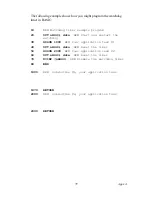
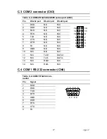
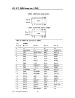
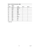
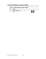
Table C.5: PC/104 connectors (CN5)
Pin Signal
Number
Row A
Row B
Row C
Row D
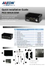
Summary of Contents for PCM-9340F-0CA1
Page 1: ...i PCM 9340 ISA STPC Elite 133 SBC with CPU 32MB SDRAM VGA LCD LAN DOC PC104 Users Manual...
Page 4: ...PCM 9340 User s Manual iv...
Page 14: ...PCM 9340 User s Manual 6 1 4 Board layout dimensions Figure 1 1 Board layout dimensions...
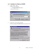
Page 48: ...PCM 9340 User s Manual 40 2 Select the Settings tab then click the Advanced Properties but ton...
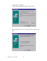
Page 53: ...45 Chapter 4 SVGA Setup 2 Select Adapter then Change...
Page 58: ...PCM 9340 User s Manual 50 2 Choose the Settings tab and press the Display Type button...
Page 59: ...51 Chapter 4 SVGA Setup 3 Press the Change button...
Page 67: ...59 Chapter 5 PCI Bus Ethernet Interface 3 Select the Driver tab then click Update Driver...
Page 72: ...PCM 9340 User s Manual 64 3 Click on Properties select the Driver tab then Update Driver...
Page 76: ...PCM 9340 User s Manual 68 10 Reboot the system...
Page 78: ...PCM 9340 User s Manual 70 3 Click Have Disk 4 Type in the path then click OK...
Page 80: ...PCM 9340 User s Manual 72...
Page 88: ...TPC 642 User s Manual 80...
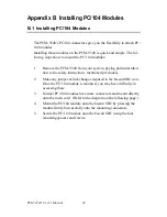
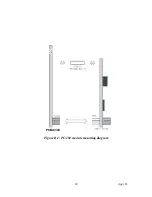
Page 91: ...83 Appx B Figure B 1 PC 104 module mounting diagram PCM 9340...
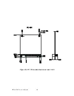
Page 92: ...PCM 9340 User s Manual 84 Figure B 2 PC 104 module dimensions mm 0 1...
Page 115: ...107 Appx E E Mechanical Drawings Appendix...
Page 117: ...109 Appx E Figure E 2 PCM 9340 Mechanical Drawing solder side...
Page 118: ...PCM 9340 User s Manual 110...