


PCM-9340 User’s Manual
22
2.19 FDD connector (CN14)
You can attach up to two floppy disk drives to the PCM-9340's onboard
controller. You can use any combination of 5.25" (360 KB/1.2 MB) and/
or 3.5" (720 KB/1.44/2.88 MB) drives.
The card comes with a 34-pin daisy-chain drive connector cable. On one
end of the cable is a 34-pin flat-cable connector. On the other end are two
sets of floppy disk drive connectors. Each set consists of a 34-pin flat-
cable connector (usually used for 3.5" drives) and a printed-circuit-board
connector (usually used for 5.25" drives). You can use only one connector
in each set. The set on the end (after the twist in the cable) connects to the
A: floppy. The set in the middle connects to the B: floppy.
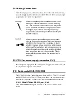
2.20 Parallel port connector (CN18)
The parallel port is designated as LPT1, and is normally used to connect
the CPU card to a printer. The PCM-9340 includes an on-board parallel
port, accessed through a 26-pin flat-cable connector, CN18. The card
comes with an adapter cable which lets you use a traditional DB-25 con-
nector. The cable has a 26-pin connector on one end and a DB-25 connec-
tor on the other, mounted on a retaining bracket. The bracket installs at
the end of an empty slot in your chassis, giving you access to the connec-
tor.
To install the bracket, find an empty slot in your chassis. Unscrew the
plate that covers the end of the slot. Screw in the bracket in place of the
plate. Next, attach the flat-cable connector to CN18 on the CPU card.
Wire 1 of the cable is red or blue, and the other wires are gray. Make sure
that wire 1 corresponds to pin 1 of CN18. Pin 1 is on the right side of
CN18.
2.21 General Purpose Input Output (CN20)
The PCM-9340 supports 8-bit GPIO through CN20. The 8 digital in- and
out-puts can be programmed to read or control devices, with input or out-
put defined. The default setting is 4 bits input and 4 bits output.
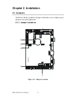
Summary of Contents for PCM-9340F-0CA1
Page 1: ...i PCM 9340 ISA STPC Elite 133 SBC with CPU 32MB SDRAM VGA LCD LAN DOC PC104 Users Manual...
Page 4: ...PCM 9340 User s Manual iv...
Page 14: ...PCM 9340 User s Manual 6 1 4 Board layout dimensions Figure 1 1 Board layout dimensions...
Page 48: ...PCM 9340 User s Manual 40 2 Select the Settings tab then click the Advanced Properties but ton...
Page 53: ...45 Chapter 4 SVGA Setup 2 Select Adapter then Change...
Page 58: ...PCM 9340 User s Manual 50 2 Choose the Settings tab and press the Display Type button...
Page 59: ...51 Chapter 4 SVGA Setup 3 Press the Change button...
Page 67: ...59 Chapter 5 PCI Bus Ethernet Interface 3 Select the Driver tab then click Update Driver...
Page 72: ...PCM 9340 User s Manual 64 3 Click on Properties select the Driver tab then Update Driver...
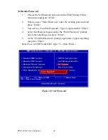
Page 76: ...PCM 9340 User s Manual 68 10 Reboot the system...
Page 78: ...PCM 9340 User s Manual 70 3 Click Have Disk 4 Type in the path then click OK...
Page 80: ...PCM 9340 User s Manual 72...
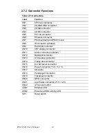
Page 88: ...TPC 642 User s Manual 80...
Page 91: ...83 Appx B Figure B 1 PC 104 module mounting diagram PCM 9340...
Page 92: ...PCM 9340 User s Manual 84 Figure B 2 PC 104 module dimensions mm 0 1...
Page 115: ...107 Appx E E Mechanical Drawings Appendix...
Page 117: ...109 Appx E Figure E 2 PCM 9340 Mechanical Drawing solder side...
Page 118: ...PCM 9340 User s Manual 110...


