19
Chapter 2 Connecting Peripherals
2.16.2 Extension flat panel connector (CN15)
CN15 consists of a 20-pin connector which is Hirose’s product no.
DF13A-20DP-1.25V. The PCM-9340 supports a 36-bit LCD panel which
must be connected to both the CN19 (40-pin) and the CN15 (20-pin). The
pin assignments for both CN19 and the CN15 can be found in Appendix
C.
2.16.3 Flat panel display connector (CN19)
CN19 consists of a 40-pin connector which can support a 24-bit LCD
panel. It is Hirose’s product no. DF13A-40DP-1.25 V
The PCM-9340 provides a bias control signal on CN19 that can be used
to control the LCD bias voltage. It is recommended that the LCD bias
voltage not be applied to the panel until the logic supply voltage (+5 V or
+3.3 V) and panel video signals are stable. Under normal operation, the
control signal (ENAVEE) is active high. When the PCM-9340’s power is
applied, the control signal is low until just after the relevant flat panel sig-
nals are present.
2.17 Audio interfaces (CN11, CN17) (optional)
The PCM-9340 is equipped with a high-quality audio interface, which
provides 16-bit CD-quality recording and playback as well as OPL3 com-
patible FM music. It is supported by all major operating systems.
2.17.1 Audio connector (CN11)
The PCM-9340 provides all major audio signals on a 16-pin flat-cable
connector, CN11. These audio signals include Microphone in (mono),
Line in (stereo), Line out (stereo), and Speaker out (stereo). If you use tra-
ditional telephone jack connectors for these audio signals, you will need
an adapter cable.
2.17.2 CD audio input connector (CN17)
Any CD-ROM drive can provide analog audio signal output when used as
a music CD player. The CN17 on PCM-9340 is a connector to input CD
audio signals into the audio controller. The audio cable of your CD-ROM
drive will be used to connect to CN17.
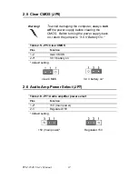
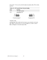
2.17.3 Audio power source setting (JP7)
The PCM-9340 is designed to work with a 5 V power supply. The
audio interface can also function normally under 5V power sup-
ply, but most audio controllers require an independent power source gen-
erated from a +12 V power supply. The independent power source avoids
the noise from the other digital circuits. The PCM-9340’s audio interface
Summary of Contents for PCM-9340F-0CA1
Page 1: ...i PCM 9340 ISA STPC Elite 133 SBC with CPU 32MB SDRAM VGA LCD LAN DOC PC104 Users Manual...
Page 4: ...PCM 9340 User s Manual iv...
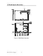
Page 14: ...PCM 9340 User s Manual 6 1 4 Board layout dimensions Figure 1 1 Board layout dimensions...
Page 48: ...PCM 9340 User s Manual 40 2 Select the Settings tab then click the Advanced Properties but ton...
Page 53: ...45 Chapter 4 SVGA Setup 2 Select Adapter then Change...
Page 58: ...PCM 9340 User s Manual 50 2 Choose the Settings tab and press the Display Type button...
Page 59: ...51 Chapter 4 SVGA Setup 3 Press the Change button...
Page 67: ...59 Chapter 5 PCI Bus Ethernet Interface 3 Select the Driver tab then click Update Driver...
Page 72: ...PCM 9340 User s Manual 64 3 Click on Properties select the Driver tab then Update Driver...
Page 76: ...PCM 9340 User s Manual 68 10 Reboot the system...
Page 78: ...PCM 9340 User s Manual 70 3 Click Have Disk 4 Type in the path then click OK...
Page 80: ...PCM 9340 User s Manual 72...
Page 88: ...TPC 642 User s Manual 80...
Page 91: ...83 Appx B Figure B 1 PC 104 module mounting diagram PCM 9340...
Page 92: ...PCM 9340 User s Manual 84 Figure B 2 PC 104 module dimensions mm 0 1...
Page 115: ...107 Appx E E Mechanical Drawings Appendix...
Page 117: ...109 Appx E Figure E 2 PCM 9340 Mechanical Drawing solder side...
Page 118: ...PCM 9340 User s Manual 110...

