


PCM-9340 User’s Manual
16
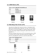
2.10.2 COM2 RS-232/422/485 selection (CN3)
This secondary port between CN2 and CN4 consists of a 14-pin, dual-in-
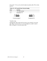
line, male header, and can be configured, via JP2 (
q.v
.), to operate in RS-
232, RS-422, or RS-485 mode.
The IRQs and address ranges for the COM ports are fixed. However, if
you wish to disable a port or change these parameters later, you can do
this in the system BIOS setup.
2.10.3 COM1 RS-232 port (CN4)
This serial port connector is the 9-pin D-SUB connector toward the left
side.
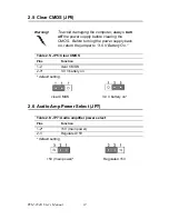
2.10.4 Share IRQ
The IRQ and the address range for COM1, 2, 3, 4 default are fixed. How-
ever, if you wish to disable the port or change these parameters later, you
can do this in the system BIOS setup. The table below shows the settings
for the PCM-9340's serial ports.
COM1-4 can share one IRQ that can be selected in BIOS setup under
Windows 98 and Windows NT. Choices are: IRQ3, IRQ4, IRQ5 or
IRQ10.
2.11 PC/104 connectors (CN5)
The PCM-9340 is equipped with a 16-bit ISA signal PC/104 connector
for future expansion. See Appendix B for details.
2.12 Ethernet Connections (CN6, LED1, LED2)
The PCM-9340 is equipped with a high performance 32-bit PCI Ethernet
interface which is fully compliant with IEEE 802.3u 10/100 Mbps
CSMA/CD standards. It is supported by all major network operating sys-
tems.
The Ethernet medium can be configured via the RSET8139.EXE program
included on the utility disk. (See Chapter 5 for detailed information.)
Table 2.8: Serial port default settings
Port
Address range
Interrupt
COM1
3F8 ~ 3FF
IRQ4
COM2
2F8~2FF
IRQ3
COM3
3E8~3EF
IRQ10
COM4
2E8~2EF
IRQ5
Summary of Contents for PCM-9340F-0CA1
Page 1: ...i PCM 9340 ISA STPC Elite 133 SBC with CPU 32MB SDRAM VGA LCD LAN DOC PC104 Users Manual...
Page 4: ...PCM 9340 User s Manual iv...
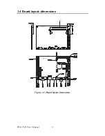
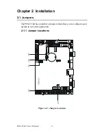
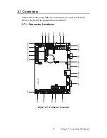
Page 14: ...PCM 9340 User s Manual 6 1 4 Board layout dimensions Figure 1 1 Board layout dimensions...
Page 48: ...PCM 9340 User s Manual 40 2 Select the Settings tab then click the Advanced Properties but ton...
Page 53: ...45 Chapter 4 SVGA Setup 2 Select Adapter then Change...
Page 58: ...PCM 9340 User s Manual 50 2 Choose the Settings tab and press the Display Type button...
Page 59: ...51 Chapter 4 SVGA Setup 3 Press the Change button...
Page 67: ...59 Chapter 5 PCI Bus Ethernet Interface 3 Select the Driver tab then click Update Driver...
Page 72: ...PCM 9340 User s Manual 64 3 Click on Properties select the Driver tab then Update Driver...
Page 76: ...PCM 9340 User s Manual 68 10 Reboot the system...
Page 78: ...PCM 9340 User s Manual 70 3 Click Have Disk 4 Type in the path then click OK...
Page 80: ...PCM 9340 User s Manual 72...
Page 88: ...TPC 642 User s Manual 80...
Page 91: ...83 Appx B Figure B 1 PC 104 module mounting diagram PCM 9340...
Page 92: ...PCM 9340 User s Manual 84 Figure B 2 PC 104 module dimensions mm 0 1...
Page 115: ...107 Appx E E Mechanical Drawings Appendix...
Page 117: ...109 Appx E Figure E 2 PCM 9340 Mechanical Drawing solder side...
Page 118: ...PCM 9340 User s Manual 110...


