background image

Assembly Instructions


8


d)


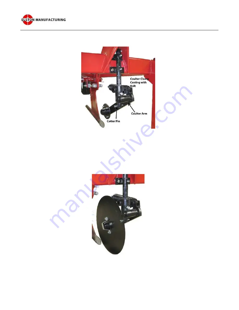
Attach  the  coulter  arm  to  the  coulter  shank  using  the  coulter  clamp  to  hold  it  in  place. 
Add the cotter pin to the hole in the bottom of the coulter shank. This pin will retain the 
coulter arm if the bolt on the coulter clamp casting becomes loose. 


e)


Bolt the coulter blade to the coulter arm. Adjust the height of the coulter blade so the bottom 
of the blade is aligned with the top of the torpedo tube. If the center line of the coulter blade 
is not aligned with the center of the knife, loosen the coulter shank clamps and reposition 
them to move them into alignment. Position the coulter clamp so the coulter is free to swing 
around an arc centered on the knife and torpedo tube. Assembly of the coulter assembly is 
now complete and should appear similar to that shown in Figure 9. 


Your GA-800 Gopher Getter is now assembled. Refer to the next chapter for additional tips and 
instructions for adjusting the machine before its first use.


Figure 8: Coulter Arm Mounted on 
Coulter Shank 


Figure 9: Completed 
Coulter Assembly 

Summary of Contents for GA-800H

Page 1: ...GA 800H OWNER S MANUAL REV D UPDATED 2021 F ...

Page 2: ...ON 1 2 GENERAL INFORMATION 2 3 ASSEMBLY INSTRUCTIONS 3 4 USING YOUR GOPHER GETTER 9 ATTACHING GOPHER GETTER TO TRACTOR 9 SETTING UP SEEDER ASSEMBLY 9 ADJUSTING DEPOSITION RATE OF BAIT 10 ADJUSTING DEPTH BAIT 10 ADJUSTING DEPTH OF COULTER 11 OPERATING INSTRUCTIONS 12 OPERATING TIPS 15 ADDITIONAL INFORMATION 15 5 MAINTENANCE 16 ...

Page 3: ...dent is not the same as working safely It is possible to do something unsafe for years and not be hurt This does not mean it is alright to continue this unsafe behavior it just means you have been lucky For example a farmer who never had a serious accident was not wearing his safety belt He rolled his tractor while moving round bales out of a ditch and he ended up underneath the tractor Thankfully...

Page 4: ...h the depth that the gophers are digging in your area The gopher getter will apply approximately two pounds per acre of Elston gopher getter bait when the burrows are spaced 20 feet apart When used with rolled oats and the seeder slide with the larger 7 8 opening the application rate will also be slightly less than 2 pounds per acre These application rates are an average for the whole field and wi...

Page 5: ...nning assembly please verify that all parts were shipped with the Gopher Getter The Gopher Getter is shipped from the factory pre assembled using the 5 pieces shown in Figure 1 Figure 1 Disassembled Parts of GA 800 Label Description 1 GA 800H Base Assembly 2 Plastic Bait Box 3 Coulter Shank 4 Coulter Blade 5 Coulter Arm ...

Page 6: ...13 Hex Nuts G 2 Seeder Slides w Pin G7 413 H 4 Seeder Slide Springs G7 429 I 1 Retaining Strap for Coulter Bearing Cap J 1 Parts Bag for Coulter Assembly 4 carriage bolts 4 lock washers 4 nuts 1 square head bolt 1 roll pin and 1 cotter pin K 1 Coulter Shank Casting L 4 3 8 Serrated Flanged Hex Nuts Figure 2 Parts Kit Inside the bait box you will find a parts kit that includes the parts shown in Fi...

Page 7: ...sembly if not already installed 2 Attach the seeder slides and bait box to the base assembly From the parts package you will need the 2 seeder slides labeled L in Figure 2 4 springs labeled K and 4 serrated flanged hex nuts labeled J You will also need the bait box a Install the four springs to the attachment points on the seeder assembly These attachment points are found just behind the clear hos...

Page 8: ...fter that place the bait box on top of seeder slides The bait box should face with the clear viewing windows facing toward the front of the machine as shown in Figure 5 and be secured with the four hex nuts d Attach the other side of the springs installed in step 2a to the holes on the seeder slides Once the step is done the unit should look like it does in Figure 6 Figure 4 Seeder Assembly Area o...

Page 9: ...ne end of the coulter shank b Mount the parts that clamp the coulter shank to the frame You will need the 2 coulter shank clamps the 2 square head bolts and the 4 bolts washers lock washers and nuts These parts should be assembled as shown in Figure 7 c Slide the coulter shank into position as shown in Figure 8 Clamp the coulter shank in place by tightening each bolts a little at a time until the ...

Page 10: ...do tube If the center line of the coulter blade is not aligned with the center of the knife loosen the coulter shank clamps and reposition them to move them into alignment Position the coulter clamp so the coulter is free to swing around an arc centered on the knife and torpedo tube Assembly of the coulter assembly is now complete and should appear similar to that shown in Figure 9 Your GA 800 Gop...

Page 11: ...ider plate in the center of the box to allow for two different baits The new hardened plastic bait box cannot deposit two different baits unless modifications are made to the plastic bait box to create a divider plate like the one installed in the original steel bait box To deposit two different baits simply fill one half of the bait box with one bait and the other half with the other choice of ba...

Page 12: ...s and potentially increase it by adding spacer plates up to a total of 3 If you are still unable to achieve the application rate you need please contact us at Elston Manufacturing at 1 800 845 1385 Adjusting Depth Bait The packer wheel determines how deep the torpedo tube or burrow builder travels through the ground The depth of the torpedo tube should match the depth of the gopher s natural burro...

Page 13: ...e set just deep enough so that the blade cuts through the debris on the surface and the major roots below the surface so that the knife passes cleanly through the soil If not the knife will catch on the uncut roots and rip the vegetation out of the ground typically resulting in blockage similar to that shown in Figure 13 Figure 12 Packer Wheel Adjustment Figure 13 Roots catching on knife due to co...

Page 14: ...on the coulter shank Lock the coulter clamp when the desired position is found For larger adjustments the bolts that hold the coulter shank to the front of the machine may also be loosened and the shank slid up or down for further adjustments Tighten the square headed bolts just tight enough to hold the shank in normal operation no more than 40 ft lbf Over tightening these bolts will likely cause ...

Page 15: ... and down pressure to the machine The advice and tips below are generalized ones for gopher getter users throughout the country For information specific to your area please speak with the dealer that you purchased the unit from your local extension agent or area farmers that use gopher getters Space your treatments 20 to 30 feet apart in straight parallel lines in areas active with gophers or bord...

Page 16: ...getter works in a huge range of soil moisture conditions or that it works well in a narrow range of conditions If you have certain types of soil or low soil moisture the gopher getter may have trouble getting to full depth where the packer wheel will turn consistently Typically it works best when the torpedo tube is sloping slightly downward into the soil a few degrees Try adjusting the angle of t...

Page 17: ...ipes or other lines in the area you will be working There is nothing worse to hit with your gopher getter Yes it has happened Always start slowing especially if you are new to the gopher getter or operating in an unfamiliar field At no point should you go faster than 5 mph In some conditions especially hard or rocky ground it will be necessary to limit your speed further Always stop quickly when t...

Page 18: ...00 lbs of bait Check if the unit needs to be greased If so lightly grease the unit at the grease points on the packer wheel hub as shown in Figure 16 and the packer wheel adjustment rod as shown in Figure 17 Check that the tire pressure is 20 psi Replace any safety decals that are no longer readable GA 800 Grease Points Figure 16 Grease Points on Packer Wheel Hub ...

Page 19: ...Maintenance 17 Figure 17 Grease Points on Packer Wheel Adjustment Rod ...

Page 20: ......

Page 21: ...ete Unit G1 Assemblies Ref Name Page 1 Knife Assembly G2 2 Coulter Assembly G3 3 Seeder Assembly G4 4 Packer Wheel Assembly G5 5 Frame Assembly G6 Please Call Elston Manufacturing for information on purchasing gopher bait poison ...

Page 22: ...t 13 1 4 Washer 14 1 4 20 x 1 1 2 Hex Head Bolt This bolt must be grade 5 or softer It is designed as a shear bolt to prevent damage when hitting underground obstructions Using a harder bolt could result in expensive repairs Ref Name Part 1 Knife Elliptical Arc G7 103 2 Torpedo Tube G7 102 3 Torpedo Point G1 105 4 3 8 16 x 3 8 Set Screw G1 143 5 Seeder Tube G9 201 6 Barbed Wye Connector G7 423A 7 ...

Page 23: ...nk G9 301 6 5 8 11 x 1 Sq Head Set Screw 2 Coulter Blade 22 G7 203 7 3 8 16 x 3 4 Sq Head Set Screw 3 Coulter Shank Clamp G9 302 8 3 8 x 2 1 2 Roll Pin 4 Single Arm Coulter G7 201 9 1 2 13 Hex Nut 5 2975 Locking Collar G7 201 19 10 1 2 Lock Washer 1 5 Coulter Assembly G9 300 11 1 2 Washer 6 14 12 1 2 13 x 6 Hex Head Bolt 13 5 16 x 2 1 2 Cotter Pin 14 1 2 13 x 1 1 4 Cage Bolt ...

Page 24: ...sy G4 231P 13 Drain Cap G4 221P 14 Plastic Hose G4 122 10 13 19 20 Plastic Bait Box Assembly G7 435P 29 GA 700 Bait Spacer Plate G7 408B Ref Name Part 15 Seeder Box Spring Not Shown G7 433 16 Seeder Slide Spring Not Shown G7 429 17 Chain Guard Not Shown G7 411 1 29 Seeder Assembly G7 400 Ref Description 18 3 8 16 x 1 Wislock Hex Bolt 19 3 8 16 Wislock Hex Nut 20 8 1 2 Sheet Metal Screw 21 9 16 of ...

Page 25: ... Part 1 18 Packer Wheel Assembly G9 400 Ref Name Part 1 Packer Wheel Swing Arm Right G9 401R 2 Packer Wheel Swing Arm Left G9 401L 3 Swing Arm Packer Wheel Axle G7 304 4 Lift Arm Connecting Nut Assy G7 308 5 Lift Arm Connecting Bolt Assy G7 309 6 Packer Wheel Hub Spacer G7 310 7 Packer Wheel Adjustment Rod G7 311 8 Lift Arm Link G7 312 9 36 Tooth Sprocket Assembly G7 314 10 Bearing Hub Assembly G7...

Page 26: ...00 G6 Ref Nam 1 Frame G9 101 2 Leg Stand G9 102 3 Snap in Pin for Legs G7 526 4 CAT 2 Top Link G8 505 5 CAT 3 Top Link G8 506 6 CAT 2 Lift Pin G8 507 7 CAT 2 to CAT 3 Lift Pin Adaptor G8 508 8 Lynch Pins G8 509 x1 x2 x2 x1 x1 x2 x2 x4 Part Qty ...

Page 27: ... found to be defective as referenced above will be corrected as referenced in the previous paragraph at no charge for parts provided by original factory or labor but will include freight paid by buyer Failure to use original factory parts voids this warranty Elston Manufacturing Inc products received by Elston Manufacturing Inc after one 1 year from original shipment date to customer will be corre...

Reviews: