


43
User Manual
MN032EN
Effective October 2017
215U-2 802.11
wireless I/O and gateway
EATON
www.eaton.com
Configuring PC networking settings for USB
You should normally be able to connect to the USB without any
additional setup. The 215U-2 is configured to automatically assign IP
address to devices connecting to the USB through DHCP. If you are
unable to connect, then you may need to set your PC to request the
IP address from the 215U-2.
(The following description is for Windows 7. Other operating systems
have similar settings)
1. On the PC, open Control Panel, then select
Network and
Sharing Center
.
2. Click “
Change Adapter Settings
” on the left of the screen.
You should see a list of available network adapters.
3. Find the correct network connection in the list. This will be
named “Local Area Connection XX” and have description
“Elpro 215U-2 USB Ethernet/RNDIS”.
4. Right click on the network connection and select Properties from
the context menu.
5. Select “
Internet Protocol Version 4 (TCP/IPv4)
” and click on
Properties
.
6. On the
General
tab, ensure
Obtain IP Address automatically
is selected.
7. Verify the Ethernet connection to the module by using the “ping”
command. Start a command window (click Start menu and type
“command” into the search box). At the command prompt, type
“ping 192.168.111.1”.
LED function
Front panel LEDs
When the module is initially connected to power, it performs
internal setup and diagnostics checks to determine if it is
operating correctly. These checks take approximately 80 seconds.
The following table shows how the LEDs appear when the module
is operating correctly.
Table 21. Front panel LEDs
LED
Condition
Meaning
PWR
Green
System OK
PWR
Red
System boot (initial or system fault)
PWR
Orange
Start of system boot
PWR
Fast Flash
System boot, stage 1
PWR
Slow Flash
System boot, stage 2
RF
Green
RF Link established
RF
Flash Off from Green
Radio Receive (RF Link established)
RF
Flash Green from Off
Radio Receive (No RF Link)
RF
Orange Flash
Radio transmit
232
Green
Transmitting RS
-
232 data
232
Red
Receiving RS
-
232 data
232
Orange
Transmitting and receiving RS
-
232 data
485
Green
Transmitting RS
-
485 data
485
Red
Receiving RS
-
485 data
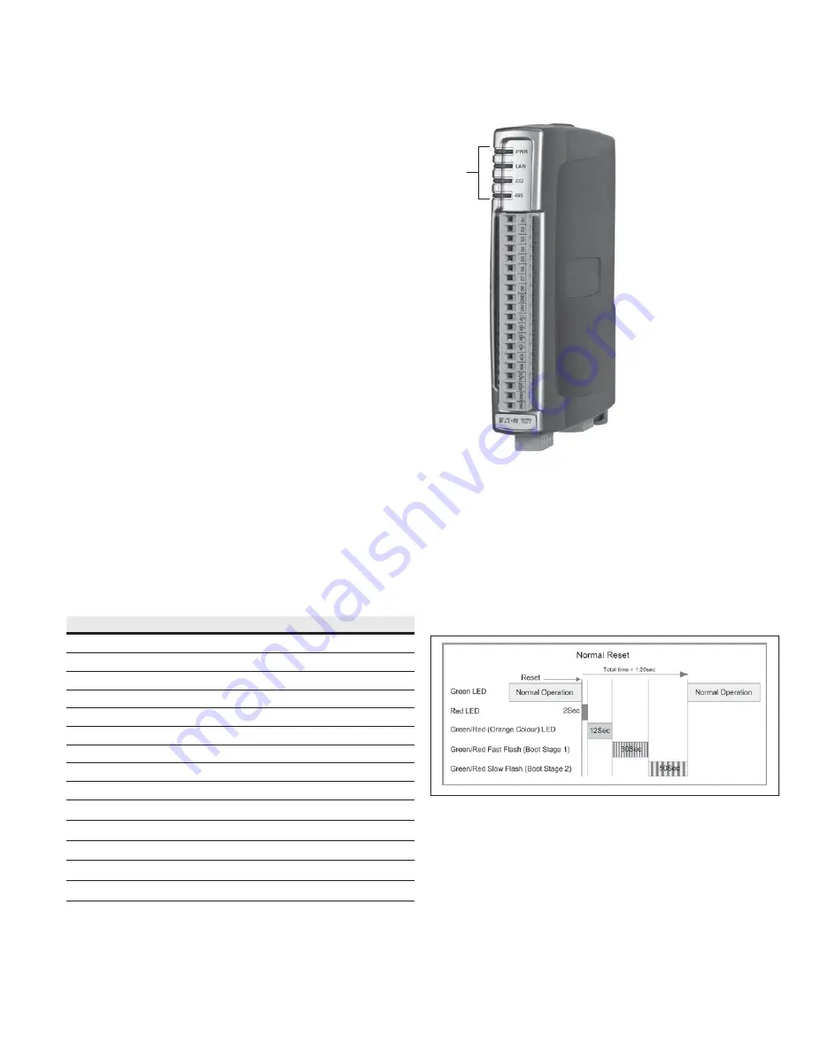
LEDs
LED boot sequence
Upon reset, the PWR LED appears solid red for about 2 seconds
(system boot), followed by 12 seconds of Orange (start of system
boot process). The PWR LED then fast flashes between red and
green for 30 seconds (stage 1 of system boot process) followed
by a slow flashes for 50 seconds (stage 2 of system boot process).
At the end of the boot sequence the PWR should appear solid
green. The time periods are approximate, and depend on the
hardware and firmware revisions.
Figure 51. Boot sequence


