background image

Elna International Corps. SA 

Xquist 

service manual 


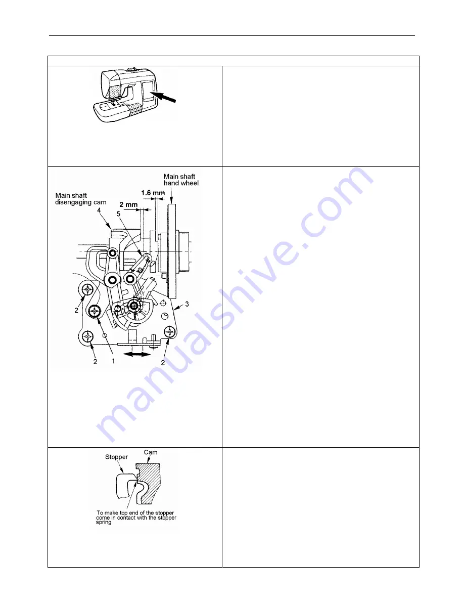
UPPER MAIN SHAFT DISENGAGING 


Location of components to be adjusted. 

6.  Remove the Under cover. 
7.  Remove the Face cover inside. 
8.  Remove the Belt cover. 
9.  Remove the Free arm bottom cover. 
10. Loose the 5 screws from the bottom plate base. 
11. Remove the Front panel. 
12. Disconnect all Front panel connectors. 
13. Disconnect all connectors on the left side from the 

microcomputer circuit board so that you have 
access to the Disengaging mechanical system. 


HOW TO ADJUST 

Relation of the position of the main shaft disengaging 
cam and the main shaft-disengaging cam. 
 
1.  Provide a clearance of 1,6 mm between the main 

shaft hand wheel and the main shaft-disengaging 
cam. Using a 1.6-mm spacer or the like. 

2.  Loosen adjustment screw 1 and the tree screws 2 

from the needle throwing STM installing plate. 

3.  Move needle-throwing STM installing plate 3 to the 

left or right to adjust the distance of 2 mm between 
the main shaft-disengaging cam 4 and main shaft 
disengaging link 5. 

4.  Tighten the tree screws 2 to fixe the needle 

throwing STM installing plate. 

Note: 
When this adjustment is performed, the needle entry 
point shifts. Perform again the needle entry 
adjustment. 
 

After this adjustment, perform the Main shaft 

disengaging stopper adjustment. 


MAIN SHAFT DISENGAGING STOPPER 

1.  Provide a clearance of 1,6 mm between the main 

shaft hand wheel and the main shaft-disengaging 
cam. 

2.  Loose the screw 1. 
3.  Make the top end of the main shaft disengaging 

stopper comes in contact with the stopper spring. 

4.  Tighten the screw 1. 
5.  After adjustment, apply grease to the sections 

below. 

  Joint of the main shaft-disengaging cam and 

the main shaft hand wheel. 

Cam section of the main shaft disengaging 

Summary of Contents for xquisit

Page 1: ...SERVICE MANUAL 08 02 Printed in Switzerland 395 902 82...

Page 2: ...s disengaged at the first turn The machine actuates the thread trimming knife to cut the thread 115 rpm and stops with its needle up Disengagement of the main shaft is released before stop 3 Automatic...

Page 3: ...n 12 Prevention of wrong setting of needle It is designed so as not to insert the needle in the wrong direction 13 Operation guide How to operate the sewing machine advice and how to sew are indicated...

Page 4: ...inding 600 15 rpm Max sewing speed in medium high speed operation For zigzag pattern 700 50 rpm When bartacking buttonholes on both sides 525 15 rpm Max sewing speed in medium speed operation For embr...

Page 5: ...c thread trimmer P 21 Base tension P Disengaging the knife P 24 Lateral position of the thread trimmer cam P 24 Moving knife guide upper P 25 Moving knife guide lower P 25 Height of the looper P 26 Bo...

Page 6: ...adjustment of the lower position see page 30 1 The transfer body is attached to the left side Check the lateral adjustment of the transfer body see page 30 2 The position of needle clamp threading ar...

Page 7: ...3 Thread has not completed and the bobbin thread is removed by the needle thread Same as 1 and 2 above The hook cover pile is excessively tilted Thread is not cough by the inner hook thread guide 4 T...

Page 8: ...rews 1 and 2 2 Remove the under cover FACE PLATE COVER 1 Loose the screws 1 and 2 2 Remove the claw section A and B using a thin screwdriver or the like BELT COVER 1 Remove the two screws 1 2 Insert a...

Page 9: ...base FRONT PANEL 1 Remove screws 1 and remove the needle plate 2 Remove the screw 2 and loose the screw 3 3 Insert a thin screwdriver into section C and remove the claw 4 Applying force to section A i...

Page 10: ...ector 8 connected to the inverter circuit board To remove the Rear panel 1 Remove the Under cover 2 Remove the Belt cover 3 Remove the Free arm bottom cover 4 Loose the 5 screws from the bottom plate...

Page 11: ...L 1 Remove the screws 3 and 4 2 Lower presser lifting lever 5 3 Lift handle 6 draw section 7 and remove the rear panel 4 Remove claw section 8 from the bottom plate EMBROIDERY UNIT FRAME OF EMBROIDERY...

Page 12: ...t screw 1 and the tree screws 2 from the needle throwing STM installing plate 3 Move needle throwing STM installing plate 3 to the left or right to adjust the distance of 2 mm between the main shaft d...

Page 13: ...5 Remove the Rear Cover see below MAIN MOTOR 1 Remove the screw 1 situation of this screw Turn the hand wheel so that the needle bar is in lowest position this screw fixe the rear cover and is to reac...

Page 14: ...R 1 Remove the two screws 1 2 Disconnect the motor 3 Remove the motor belt MAIN MOTOR How to adjust the motor belt Adjust the motor belt tension by moving the motor up or down and after the adjustment...

Page 15: ...of thread retaining plate A temporarily determine the height and fix it 2 Turn the bobbin thread intermediate gear by hand to move thread retaining plate A in the state that the throat plate and the h...

Page 16: ...SA Xquist service manual Adjust the height so that the clearance provided between the upper plane rib which is higher of the bobbin rib and the bottom end of thread retaining plate A is 0 to 0 3 mm at...

Reviews: