


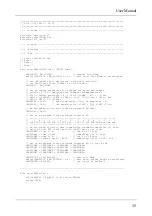


//-----------------------------------------------------------------------------
UINT8 getCAN0(void) {
UINT8 c;
while((CAN0RFLG & BM_RXF) == 0) ; // wait until CAN RX data pending
c = *(C4); // save data
CAN0RFLG = BM_RXF; // clear RX flag
return c;
}
//-----------------------------------------------------------------------------
void putCAN0(UINT16 canid, UINT8 c) {
while((CAN0TFLG & BM_TXE0) == 0) ; // wait until Tx buffer released
*(C0) = canid >> 8; // destination address
*(C1) = canid & 0xe0;
*(C4) = c;
*(C12) = 1; // one byte data
*(C13) = 0; // priority = 0 (highest)
CAN0TFLG = BM_TXE0; // initiate transfer
}
//=============================================================================
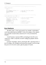
Bus Interface
The MCU ports A, B, K and (partly) E are related to the Multiple-
xed External Bus Interface (MEBI). On the S12compact, all bus signals
are accessible via two header connectors (X7, X8; not mounted by
default).
A small memory expansion PCB can be plugged onto these two
connectors, which is especially useful for debugging purposes (Flash
emulation).
In Single Chip Mode, which is the default MCU operating mode of
the S12compact, the Multiplexed External Bus Interface is not used and
the ports A, B, K can be used as general-purpose I/O-ports.
S12compact
36