


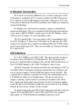


implemented. The MCU can read the /RTS output using port pin PM6,
while PM7 controls the /CTS input of the USB-UART.
Transmit- and receive-activities can be displayed using two LEDs.
Their anodes must be wired to VCC (5V), while the cathodes have to be
connected to /RXLED and /TXLED (X4/67+68), respectively.
/PWREN is set by IC15 according to the enumeration status of the
USB device. This signal can be detected by MCU port pin PM4. The
control signal /SLEEP is low if IC15 is in Suspend-Mode, PM5 is used
to read this signal.
BR11 must be closed if a system reset should also reset the
USB-UART, which is normally not required. The USB-UART has an
independent power-on reset circuit, so, normally it does not need an
external reset source. If BR11 is closed, any system reset will temora-
rily remove the USB device from the bus "logically". When the reset
condition has ended, the device needs to be re-enumerated by the
USB-Host.
The serial EEPROM IC16 can hold configuration data for the
USB-UART. If IC16 is erased (default delivery state), the USB-UART
uses standard descriptors to answer descriptor requests from the host.
User descriptors (VID, PID, strings, serial numbers etc.) can be
downloaded to EEPROM using a PC-based utility program (provided
by FTDI). The programming can be done in-circuit via USB.
Please note: If the USB-Option is equipped, the IF-Module connec-
tion X3 is not available.
S12compact
24