ELKC1M1 4GSM ElkCommBd Communicator
Page 5
Step 4: Mounting and Connecting to the M1 Control.
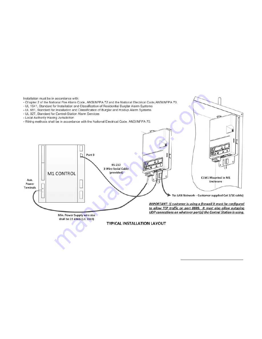
C1M1 is designed to be mounted in the top right corner of the M1 Control Enclosure. Be sure to perform a radio signal strength test
PRIOR to permanent mounting of the M1 Control or the C1M1.
Mounting
4.1. From the inside install the supplied #6 x 3/8 self tapping mounting screw in the hole centered just above the top right knockout
of the M1 enclosure. Leave the screw sticking out 1/16". The keyhole slot on the back of the C1M1 will slide onto this screw.
4.2. Remove the 1/2" antenna knockout on the top and right side of the enclosure (just above the mounting screw location).
4.3. Hold the C1M1 at about a 5 degree angle and thread its antenna up and through the top antenna knockout. While doing so,
move the unit to the right until the keyhole slot on the back engages the mounting screw. Slide the unit over and down onto the
screw.
4.4 The bottom of the C1M1 will straddle a basket handled designed for attachment of wiring with a zip-tie. After all testing has been
completed use the included zip-tie to final fix the unit to this basket handle.
Wiring Connections
4.4 Make certain the M1 and C1M1 are not powered on while making any connections.
4.5. Connect a two-conductor Red/ Black power cable from the Positive and Negative input terminals on the C1M1 to the Positive
and Negative output terminals of one of the Auxiliary Power outputs on the M1 Control. Be mindful to observe proper polarity.
4.6. Plug the supplied 3-wire serial cable (black cable with white 3-pin connector and 9 pin serial connector) into the C1M1 and then
into the main serial port #0 on the upper right edge of the M1 Control.
4.7. Connect a Cat5/5E RJ45 terminated LAN cable (not supplied) from the C1M1 to the Customer's LAN switch or router.
4.8. Make sure all connections including the screw-on dipole antenna are correct and secure. Turn on the M1 Control power. The
C1M1 should power up.
4.9. Observe the C1M1 LEDs and the 7 segment display for activity. The unit will immediately attempt to obtain an IPv4 address via
DHCP from the customer's LAN router, and display that IP address during the first few minutes after power application.
Example:
A 1 9 2 . 1 6 8 . 0 . 1 0 0


