3.
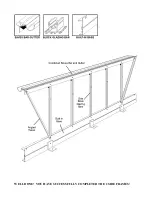
Lay out the components of the frame on the ground as though you were standing on the inside
i.e. with the internal bolt slots uppermost. Ensure that, having correctly identified the roof
from the side corner bars, left and right hands (see previous text) you have the roof bars with
the letter ‘R’ (indicating ridge) at the top on the outside, i.e. towards the ground.
(Key point).
4.
Slide a bolt into the alternative bolt slot of all 4 corner bars (see diagram for details) 1 at the
top and 1 at the bottom. Put a nut on and lightly tighten,
leaving them approx. 2” from the end of each bar. These
will be used later in the general assembly.
5.
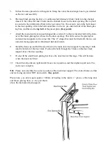
Starting at the apex (2 corner bars opposite each other
marked ‘R’) slide 1 bolt into the facing bolt slot i.e. the one
that is facing upwards and is set at 90º to the alternative bolt
slot– 4 above.
(Key point).
6.
Place the ridge gusset plate (larger of the 2 types) over the
bolt, slide the plate left or right until the slotted hole in the
plate lines up with the locating hole in the flange nearest to
the end of the corner bar. Put nuts on both bolts i.e. flange and plate, finger tip
tighten only
. (Key point).
7.
Do exactly the same with the other roof corner bar ensuring that the two bars are
pressed tight up together behind the ridge gusset plate.
8.
Now moving to the eave gusset assembly, slide one bolt into the facing bolt slot (the one
that is facing upwards and is at 90º to 4 above). Place the eave gusset plate (smaller of
the 2 types) onto the bolt and move it left or right until the next hole in the plate lines up
with the locating hole in the top of the side corner bar. Place a bolt through the hole and
put a nut on finger tip tight only.
(Key point).
At this stage do not put a nut on the top
bolt.
9.
Do the same with the other part of the eave gusset plate, ensuring that both corner bars
are tight up against each other behind the eave plate.
10. Repeat steps 8 and 9 at the other corner with another eave gusset plate.
11. Attach the bottom built in base cill, marked “rear end” in the box, to the left and right
hand side corner bars by inserting a bolt into the facing bolt slot of the corner bar. Line the
bolts up with the 2 slotted holes at the end of the cill, put nuts on and tighten up ensuring that
the corner bars are pushed right down into the angle of the cill.
(Key point).
Summary of Contents for 7'5" WIDE TITAN
Page 1: ......
Page 2: ......
Page 3: ......
Page 9: ...WELL DONE YOU HAVE SUCCESSFULLY COMPLETED THE 2 SIDE FRAMES ...
Page 11: ...REAR END ASSEMBLY ...
Page 16: ...DOOR END ASSEMBLY ...
Page 32: ...ELITE 1806 ...


