


69
English
11.5.9 Replacing the gas spring
• A 500 N gas spring presses against the left arm of the
feed roller. This gas spring is important because it will
ensure that the feed roller is pressed against the green
waste. This will ensure that the teeth have the best pos-
sible grip on the wood. This gas spring will loose pressure
in due course and it should be replaced.
(1)
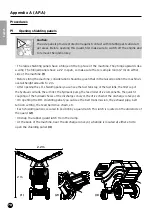
• To quickly replace the gas spring, we recommend using
a lever as indicated in the drawing below.
(2)
• Position the fork of the lever across the attachment
point of the gas spring with the frame. Next, pull the lever
towards you and ensure the tension is maintained.
(3)
• Next, remove the securing bolt (M8) (A/F 13)
• Now, move the lever backwards, which will release the
tension on the gas spring until it is fully extended.
• Remove the gas spring from the arm. (A/F 13)
Gas springs are available from an authorised ELIET
dealer with order number: BV 521 010 001
• Refi t the new gas spring using a reverse sequence to that given for removal.
• Always install the piston rod on the arm and the piston body on the frame.
It is extremely important that you ensure there is a correct alignment when installing a new
gas spring. If you notice that the gas spring is not installed aplomb, fi t a few spacers where it
is secured to the frame. Failure to do so, will cause the seal to be under additional pressure and
promote leakage. You will have to again replace the gas spring fairly quickly.
Caution:
Always ensure that the gas spring cannot slide away when retracting.
The 500 N force is suffi cient to break bones or cause serious bruising.
Be careful.
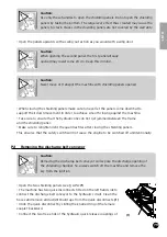
11.5.10 Replacing the elastic coupling
An elastic coupling has been used for vibration-
free transmission and a minimum pressure on the
bearings of engine and hydro pump. This coupling
consists of three components:
• Aluminium coupling assembly to the side of the
petrol engine (Part No. BA 201 232 001)
(1)
• Aluminium coupling assembly to the side of the
pump (Part No. BA 201 220 101)
(2)
• Rubber fl ector (elastic segment)
(Part No. BA 201 240 000)
(3)
(1)
400
55 13
35
(2)
(3)