


Constraints for Use (Safety requirements for integration)
- 20 -
8.
The worst case reaction times of relay contacts OC, SR1 and SR2 when a safety function is triggered is
<55 ms and concerning the eSGC <45 ms.
9.
Constraints for Installation of magnetic tape according to its instruction manual must be observed
10.
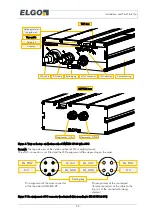
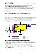
A tape presence detector securing the risk of demolition of the magnetic tape must be integrated into the
safety circuit, see also the installation schemes (Figure 8, Figure 9and Figure 12)
11.
The OC-actuator must always be integrated in the safety circuit, see Figure 8 and Figure 9.
12.
The eSGC-actuator must be connected to an electromechanical braking element following the idle current
principle.
13.
The inspection controls signals must be connected following Figure 8.
14.
The earthling lug on the LIMAX33 CP-00 must be connected to protection earth.
15.
The inductivities switched by the actuators (examples: contactors at the end of safety circuit switched by
OC, SR1 or SR2; tripping coil of electronic safety gear - switched by eSGC) must be equipped by suitable
interference suppression measures; e.g. recovery diodes for DC-circuits; RC-circuits for AC-circuits.
16.
The safety functions over speed final tripping, pre-triggered stopping system and ETSL must fulfill SIL 3
and therefore the PFHD of the whole functional chain must be smaller than 100 FIT. Concerning the PFHD
capability of the LIMAX33 CP-00 (
17.
The braking element connect to the eSGC actuator may be:
a)
an electronic triggered safety gear,
b)
a conventional safety gear triggered by a conventional speed governor, which in turn is triggered
via the remote triggering of the LIMAX33 CP-00
c)
another braking element the safety gear or the machine brake (e.g. a rope gripper)
The braking element following a.) can always be chosen, no matter if safety function “over speed final
tripping” UCM, pre-triggered stopping system or working platform should be fulfilled via the eSGC-
actuator.
The braking element following b.) can be chosen, no matter if safety functions “UCM”, “pre-triggered
stopping system” or “working platform” should be fulfilled via the eSGC-actuator.
Overspeed (final tripping) following EN81-20 §5.6.2.2.1.1a.) is normally fulfilled by the conventional
speed governor in this case.
The braking element following c.) can only be used for the safety function “UCM”. The safety functions
“working platform” or “pre-triggered stopping system” can only be fulfilled by a brake acting on the
rails (due to EN81-20).
18.
The CAN bus is not intended to be used for safety relevant purposes.
19.
After commission, the floor table must be checked before the lift is allowed to be released for public use.
20.
A power cycle or a reset must be d to the LIMAX33 CP-00 at least once per year.
21.
The reaction time of the electronic safety gear (resp. other braking element on eSGC) is in the responsibil-
ity of the user. In the technical data
7.3, “Solid state contact (eSGC) reaction time” a time of 45 ms is
defined. This concerns to the time from appearance of a hazardous speed until solid state switch is
opened and therefore voltage on trip is switched off. The reaction time of the electronic safety gear is the
time from opening of the solid state switch until braking force is present. The reaction time of the electron-
ic safety gear consists of an electrical and mechanical portion. Concerning the electrical portion refer also
to topic
22.
It must be ensured that the eSCG-braking element trips (goes to safe state) if the voltage on its trip coil
amounts to 2 V or below.
23.
The trip coil of the eSGC-braking element connected to the eSGC-actuator must fulfill the following con-
ditions (refer also to Figure 5),
Remark: if resistance or inductivity of the wire from eSCG-connector to the
trip coil have a relevant magnitude, this must also be taken into account
a.
L < 1.5H
b.
Current consumption < 1A => R > 24Ohm @24V (the eSGC – actuator is secured inside the
CP with a 1A self-resetting polyfuse)
c.
L/R > 1ms (recommended): for L/R << 1ms there is a danger that the braking element would
fall during the test of the eSGC-actuator, refer also to chapter
d.
L/R < 10 ms (recommended). The L/R influences – beside the mechanical construction – the time
for the braking element to fall. A big L/R causes a slower falling of the current through the coil af-
ter the voltage has been switched off. The current again influences the holding force of the coil,
refer also to topic
Summary of Contents for LIMAX33 CP-00 SERIES
Page 91: ...91 Notes...


