


ATTENTION
Crushing or tension will damage the electrical cables.
►
Install all electrical cabling so that it is not subject to any
crushing or tensile load
►
Observe the bending radii of cables (at minimum 50 mm).
►
Route connecting cables in a downward loop to prevent
water running into the drive.
Damage to the drive due to the effect of impact forces.
►
Slide the drive into the shaft. Never knock the drive in or
use force!
►
Take care not to drop the drive!
Damage or destruction to the drive by drilling.
►
Never drill the drive!
Important
Only fasten the RolMotion/D+ M-868 to the designated fas-
tening elements.
Fixed installed control devices need to be attached so they
are visible.
• The blind must be attached to the winding shaft.
•
The profile tube must have sufficient clearance from the
motor tube.
•
Make sure there is sufficient axial play (1 - 2 mm)
Installation in profile tubes
Ⓐ
Push drive with relevant adapter and
crown into the profile tube.
Install the motor cable so it is pro-
tected to prevent damage from the
driven part.
Ⓑ
Secure the counterpart support to
prevent axial movement, e.g. screw
or rivet on the idler.
Secure the drive axially in the
support!
Ⓒ
Attach the blind to the shaft.
Only operate the drive horizontally, as intended, with the
connection cable leading out from the side and out of the
blind winding area.
5.2 Electrical connection
WARNING
Faulty electrical connections constitute a fatal hazard.
Risk of electric shock.
►
Prior to initial commissioning, check the PE wire is cor-
rectly connected.
ATTENTION
Damage to the RolMotion/D+ M-868 due to incorrect
electrical connection.
►
Prior to initial commissioning, check the PE wire is
correctly connected.
Ingress of moisture will damage or even destroy the
RolMotion/D+ M-868.
►
For devices with protection class IP 44, the custom-
er-side connection of the cable ends or plugs (cable feed-
through) can also be implemented according to protection
class IP 44.
4 | EN
©
elero
GmbH
Assembly | Mechanical fastening | Electrical connection
►Selection of motor bearing by torque specifications.
►
The drive must be protected with all the enclosed safety
devices.
►
Check for correct engagement on motor bearing and the
correct screw tightening torques.
WARNING
Risk of injury due to electric current.
Risk of electric shock.
►
Always have electrical work carried out by an authorised
electrician.
Risk of injury due to electric current.
Possible danger due to parts that are faulty becoming
energised.
►
Electrical connection is described in the operating and
assembly instructions, including cable routing.
CAUTION
Risk of injury due to malfunctions as a result of incorrect
assembly.
Drive is overwound and may destroy parts of the
application.
►
For safe operation, the end positions must be set/taught
in.
►
Manufacturer training is available for specialist
companies.
ATTENTION
Power failures, breaking of machine parts and other
malfunctions.
►
For safe operation, assembly must be correct and the
end position adjustments will have to be carried out upon
commissioning.
Damage to RolMotion/D+ M-868 due to ingress of moisture
►
On devices with protection class IP 44, the ends of all
cables or plugs will need to be protected from ingress of
moisture. This measure needs to be implemented imme-
diately after removing the RolMotion/D+ M-868 from the
original packaging.
►
The drive must be installed so that it cannot get wet.
Important
In its delivery condition (factory setting), the RolMotion/D+
M-868 will be in commissioning mode.
►
The end positions
will need to be set (see section 5.6). This action is
self-programmed.
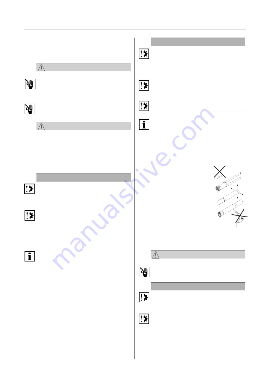
Optimal use of the radio signal.
►
Extend the antenna as far as possible. If reception is
poor, adjust the antenna.
►
Do not kink, shorten or extend the antenna.
►
Do not position the two radio drives closer than the mini-
mum distance of 15 cm.
5.1 Mechanical fastening
Important preliminary consideration:
The working area around the installed drive is usually
very small. For this reason, obtain an overview of how the
electrical connection has been implemented prior to the
mechanical installation (see section 5.2) and make the
necessary changes beforehand.


