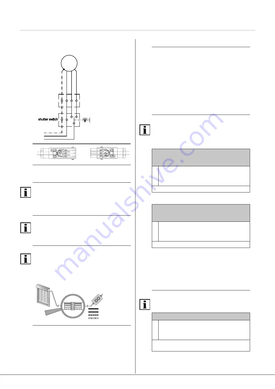
5.3 Connection example: InDrive M30/1.6 RH
230 V / 50 Hz
1 0 2
reseau electrique
L
N
PE
230V/50Hz
ver
t-j
aune
br
un
no
ir
ble
u
de volet
M
1~
1 0 2
rete
L
N
PE
230V/50Hz
ver
de
/g
ial
lo
m
ar
rone
ner
o
blu
M
1~
1 0 2
Netz
L
N
PE
230V/50Hz
gr
ün/
gel
b
br
aun
sc
hw
ar
z
bla
u
oder -taster
M
1~
1 0 2
power grid
L
N
PE
230V/50Hz
gr
ee
n/
Yel
low
br
own
bl
ac
k
blu
e
junction box
M
1~
boiter de
scatola di
derivatione
3
2
1
3
2
1
Fig. 4 Connection diagram InDrive M30/1.6 RH 230 V/
50 Hz and cable assignment when using
Hirschmann plug connection STAS-3
Important
The motor controls in the up/down direction must be locked
against each other.
A reversing delay of at least 0.5 seconds must be ensured.
5.4 Parallel circuit
Important
You can connect several InDrive M30/1.6 RH in parallel.
Please note the maximum switching capacity of the control
unit.
5.5 Commissioning
Important
The drive is in commissioning mode when delivered.
►The end positions must be configured using the
elero
assembly cable
►
The assembly cable may only be connected to
commission the drive and for adjustment operations
%ODX1HXWUDOOHLWHU
6FKZDU]
%UDXQ
*UQJHOE
HOHUR
HOHUR
%ODX1HXWUDOOHLWHU
6FKZDU]
%UDXQ
*UQJHOE
Fig. 5 Connection for assembly cable
►
Switch on mains.
►You can now configure the end positions using the
elero
assembly cable.
5.6 Setting the end positions and release
Important preliminary consideration:
Decide on a specific release function before actually setting
the end positions (different combination options as per the
following designs).
This saves you unnecessary configuration work!
Press the adjustment keys until the drive signals the switch
to programming mode by means of a short automatic stop.
You can now set the end positions. Programming mode is
finished once both end positions have been set.
5.6.1 Release function for end positions
If an end position was taught in at a limit stop, a release can
also be enabled for the slats.
Important
The release function (for variants B to D) is activated in
a single step when programming the end positions (see
chapters 5.6.7 to 5.6.9)!
5.6.2 Release function in initial position
For variant B (see chapter 5.6.7) and variant C
(see chapter 5.6.8):
Activate release function in initial position
1
Using the assembly cable while holding down the
[
UP ▲
] button from instruction
①
(chapters 5.6.7 and
5.6.8), press the [
DOWN
▼] button (simultaneously)
and hold down both buttons until the slats stop.
The release function in initial position is activated.
5.6.3 Release function in end position
For variant C (see chapter 5.6.8) and variant D
(see chapter 5.6.9):
Activate release function in end position
1
Using the assembly cable while holding down the
[
DOWN
▼
] from instruction
①
(chapters 5.6.8 and
5.6.9), press the [
UP ▲
] button (simultaneously) and
hold down both buttons until the slats stop.
The release function in end position is activated.
5.6.4 Changing/deleting end positions and
deleting the release function
It is not possible to change or delete individual end
positions. This is always done in pairs (initial position and
end position at the same time).
When the end positions are deleted, the setting for the
optional release function will also be lost.
Important
The protection for the slats is only adapted to the slats after
a complete, uninterrupted extension and retraction (cycle).
Changing/deleting the end positions
1
Starting from a central slat position, use the assembly
cable to simultaneously press both direction buttons
[
UP
▲
] + [
DOWN
▼
] and hold them down until the
slats briefly move up and down.
The end position settings have been deleted.
The end positions can be reset.
©
elero
GmbH
EN | 5
Commissioning | Configuration of end positions and release


