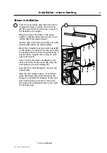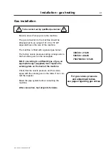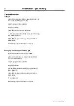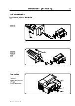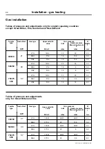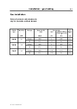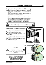
Installation - electric, steam and gas heating
487 18 39 01 - 300/500/750 - GB
32
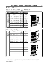
Electric installation 750/75/650
To be carried out by qualified personnel
The tumble dryer must be given a fuse group of
its own.
Connecting the cable:
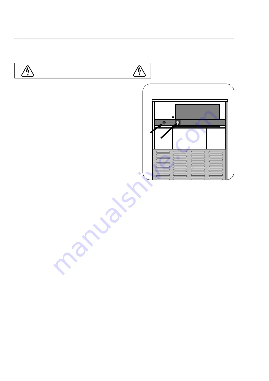
Remove the top plate at the back of the tumble
dryer to connect the cable through cable glands A
to locking power switch clamp B or to terminal
strip C.
Interlockable switch B is mounted on machines for
countries within EU and EEA (as provided for in
the directive on mechanical engineering regarding
power switches for electrical supply during servic-
ing work).
Cable dimension:
For calculation of the connection cable dimen-
sion, please refer to local guidelines.
Fuse size and effect are given on the pages to follow.
Function check, see next page.
(NB: Correct direction of rotatio
n is important!)
The tumble dryer must be equipped with sup-
plementary protection in accordance with
heavy current regulations.
L3 L2 L1 N
B
A
C
Summary of Contents for TT300
Page 1: ...Operating and installation manual TT300 TT500 TT750 487 1839 51 01 99 31 ...
Page 2: ......
Page 4: ......
Page 6: ......
Page 18: ...Instructions for use 18 487 18 39 01 300 500 750 GB ...
Page 26: ...General installation 487 18 39 01 300 500 750 GB 26 ...
Page 38: ...Installation electric steam and gas heating 487 18 39 01 300 500 750 GB 38 ...
Page 46: ...Installation electric steam and gas heating 487 18 39 01 300 500 750 GB 44 2 ...


