General installation
487 18 39 01 - 300/500/750 - GB
22
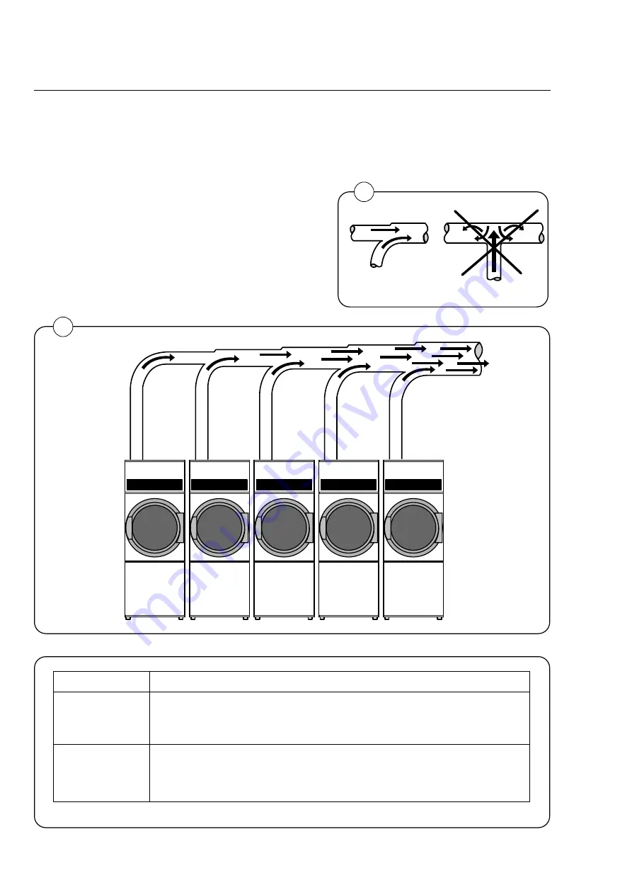
When installing several machines on a shared
evacuation pipe, increase the area of the pipe
with each additional machine so that each
machine will be working at the same air resis-
tance. Fig. 2 and the table show in simplified form
how the evacuation pipe should look.
Note: To keep the air flowing, use bends
(not T-pieces). See Fig. 1.
1
2
3
4
5
6
7
8
9
10
200
280
315
355
400
450
475
500
535
560
0.15
0.30
0.45
0.60
0.75
0.90
1.05
1.20
1.35
1.50
Number of tumble
dryers
Air outlet pipe
diameter, mm
Required area of
fresh-air inlet, m2
Tumble dryer evacuation system
Evacuation system for installation of several machines with
a shared evacuation pipe
1
2
Each machine requires a 400 x 400 mm fresh-air inlet opening.
Summary of Contents for TT300
Page 1: ...Operating and installation manual TT300 TT500 TT750 487 1839 51 01 99 31 ...
Page 2: ......
Page 4: ......
Page 6: ......
Page 18: ...Instructions for use 18 487 18 39 01 300 500 750 GB ...
Page 26: ...General installation 487 18 39 01 300 500 750 GB 26 ...
Page 38: ...Installation electric steam and gas heating 487 18 39 01 300 500 750 GB 38 ...
Page 46: ...Installation electric steam and gas heating 487 18 39 01 300 500 750 GB 44 2 ...


