www.electroluxaircomfort.com 17
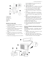
1 Valve body
2 Valve stem
3 Charge port
4 Stopper
5 Flare nut
6 Cap
Using the vacuum pump
1. Fully tighten the fl are nuts at connection
point A, B, C and D.
2. Connect vacuum hose between charging
port and the manifold.
3. Connect the other charge hose between
manifold and the vacuum pump.
4. Fully open the handle Lo of the manifold
valve.
5. Operate the vacuum pump to evacuate.
6. Slightly loosen the fl are nut of the Lo valve
on the gas pipe side.
7. Check if air is entering (noise of the vacuum
pump changes and compound meter indi-
cates 0 instead of minus).
8. Tighten the fl are nut.
9. Make evacuation for 15 minutes or more and
check that the compound meter indicates
-7.6 x 10⁵ μmHg (-1x10⁵ Pa) (-0,7Bar).
10. Fully close the handle Lo of the manifold
valve and stop the operation of the vacuum
pump.
11. Turn the stem of the packed valve B about
45° counterclockwise for 6~7 seconds after
the gas comes out, then tighten the fl are nut
again.
12. Make sure the pressure display in the pres-
sure indicator is a little higher than the at-
mosphere pressure. This to verify if the refrig-
erant does fl ow correctly through the tubes.
13. Remove the vacuum hose.
14. Replace the charging port cap.
15. Fully open the packed valve stems B and A.
16. Securely tighten the cap of the packed
valves.
Outdoor condensate drainage (heat-pump
unit only)
During heating operation, condensate water and
defrosting water must be drained through the
drain hose.
1. Install the outdoor drain connector in a Ø 25
mm hole on the base plate.
2. Attach the drain hose to the connector so
that water in the outdoor unit can be drained.
The hole diameter 25 must be plugged.


