Electrolux CXH09HL1W User Manual Download Page 15

www.electroluxaircomfort.com  15

Indoor unit

Installing the mounting plate

1.  Install the mounting plate horizontally.
2.  Fix the mounting plate to the wall with 

screws. Make sure that the mounting plate is 
fi xed fi rmly enough to support approximately 
60 kg. The weight must be evenly shared by 
each screw.

Drill piping hole

1.  Slant the piping hole (Ø 55 mm) on the wall 

slightly downward to the outdoor side.

2.  Insert the piping-hole sleeve into the hole to 

prevent damage to the connection piping 
and wiring.

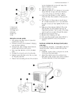
Installing the drain hose

1.  Connect the drain hose to the outlet pipe 

of the indoor unit. Bind the joint with rubber 
belt.

2.  Put the drain hose into the insulating tube.
3.  Wrap the insulating tube with wide rubber 

belt to prevent the insulating tube from shift-
ing. Slant the drain hose slightly downward 
for smooth drainage of the condensate 
water.

NOTE

•  The insulating tube must be connected reli-

ably with the sleeve outside the outlet pipe. 
The drain must be slanted downward slightly 
without distortion, bulge or fl uctuation. Do 
not put the outlet of the drain hose in water 
to prevent the drain hose from freezing.

Electrical wiring indoor unit:

CAUTION

•  Check the wiring to make sure that there is 

no short circuit. Incorrect wiring can cause 
malfunction.

1.  Open the front panel.
2.  Remove the wiring cover.
3.  Fix the mains cord to the terminal board (as 

shown).

4.  Guide the mains cord through the hole at the 

back of the indoor unit.

5.  Install the cord anchorage and wiring cover.
6.  Close the front panel.

NOTE

•  The electrical wiring between the indoor unit 

and the outdoor unit must be connected by 
a qualifi ed electrician.

•  Tighten the terminal screws tightly.
•  After tightening the screws, pull the wire 

slightly to confi rm whether it’s fi rm or not.

•  Make sure that the electrical connections are 

properly grounded to prevent electric shock.

•  Make sure that the wiring connections are 

secure and that the cover plates are properly 
mounted to prevent electric shock.

Installing the indoor unit

The piping can be output from the right, the right 
rear, the left or the left rear.
1.  When routing the piping and wiring from the 

left or right of indoor unit, cut off the tailings 
from the chassis when necessary.

2.  Remove the piping from the body case.
3.  Wrap the piping, the mains cords and the 

drain hose with the tape.

4.  Guide the piping, the mains cords and the 

drain hose through the piping hole.

5.  Firmly hang the mounting slots of the indoor 

unit on the upper hooks of the mounting 
plate.

6.  The installation site must be at least 50 cm 

above the fl oor surface.

Installing the connection pipe

1.  Align the centre of the piping fl are with the 

related valve.

2.  Screw in the fl are nut by hand and then tight-

en the nut with spanner and torque wrench. 
Refer to the following table.

No.

Colour

1

Blue (Neutral)

2

Black

3

Brown

4

Yellow (Ground)

Summary of Contents for CXH09HL1W

Page 1: ...www electroluxaircomfort com A www electrolux com A CXH09HL1W EN SPLIT INVERTER USER MANUAL CXH12HL1W HEAT PUMP ...

Page 2: ...use it you can be safe in the knowledge that you ll get great results every time Welcome to Electrolux Electrolux Central Vacuum Systems 5855 Terry Fox Way Mississauga ON L5V 3E4 Canada Visit our website Get usage advice brochures trouble shooter service information www electroluxaircomfort com CUSTOMER CARE AND SERVICE We recommend the use of original spare parts When contacting Service ensure th...

Page 3: ...o not switch on and off the unit frequently If the voltage is too high electrical elements will be damaged easily If the voltage too low the compressor will vibrate fiercely and damage the cooling system or the compressor Electrical components cannot be operated Make sure that the unit is properly grounded to prevent electric shock Do not attempt to repair the unit yourself to prevent electric shoc...

Page 4: ...ose 16 Drain connector REMOTE CONTROL The remote control can be used for different models Depending on the model some functions on the remote control might not be available CAUTION Do not drop or throw the remote control Do not pour liquid onto the remote control Do not expose the remote control to direct sunlight Do not place the remote control in areas where it is very hot NOTE Make sure that th...

Page 5: ...ton to set the time Keep the button pressed for two seconds to accelerate the process Press the CLOCK button again to set the clock The clock symbol stops blinking After battery replacement 12 00 PM will be shown If the clock symbol is visible the actual time will be shown If the clock symbol is not visible the timer will be shown 23 LIGHT Press the button to switch the display of the indoor unit ...

Page 6: ... SLEEP CANCEL Default setting SLEEP CANCEL SLEEP 1 In COOL and DRY mode Sleep status after 1 hour of operation The temperature will increase by 1 C Sleep status after 2 hours of operation The temperature will in crease by 2 C After this time the unit continues to use the new temperature In HEAT mode Sleep status after 1 hour of operation The temperature will de crease by 1 C Sleep status after 2 h...

Page 7: ...E button to set the operation mode 4 Press the UP and DOWN buttons to set the temperature Note It is unnecessary to set the temperature in AUTO mode 5 Press the FAN button to set the fan speed 6 Press the SWING H and SWING V buttons to set the swing Optional operation 1 Press the SLEEP button to enable or disable the sleep mode 2 Press the TIMER ON and TIMER OFF but tons to enable or disable the t...

Page 8: ...trol within its trans mitting and receiving range Operate the remote control at least 1 m away from your TV set or stereo sound set Aim the remote control at the receiver of the main unit to improve the receiving sensitivity of the main unit If the remote control transmits a signal the transmitting symbol will blink for 1 second The bell will ring if the main unit receives the signal If the remote...

Page 9: ...air filter The air filter must be cleaned every 3 months WARNING Do not touch the fin of the indoor unit to prevent personal injury CAUTION Do not use water above 45 C to clean the air filter to prevent deformation or discolouration 1 Open the front panel 2 Remove the air filter 3 Remove dust from the air filter using a vacuum cleaner 4 If the air filter is dirty clean the air filter with warm water and a...

Page 10: ...ound of friction caused by expansion and or contraction of the front panel or other parts due to the change in temperature The unit cannot be started Is the unit disconnected from the power supply Is the mains plug loose Is the circuit protection device tripped off Is the voltage higher or lower tested by professionals Is the timer function used correctly The cooling heating effect is poor Is the ...

Page 11: ...disconnect the unit from the power supply and contact an authorised service centre Water is leaking from the indoor unit Immediately stop operation disconnect the unit from the power supply and contact an authorised service centre The air switch or protection switch often interrupts power supply Immediately stop operation disconnect the unit from the power supply Water or other liquid is splashed ...

Page 12: ... energy saving Do not overcool or overheat Setting the temperature at a moderate level helps energy saving Cover windows with a blind or a curtain Blocking sunlight and air from outdoor is favourable for cooling Clean air filters every two weeks Clogged air filters lead to inefficient operation and energy waste Tips for relative humidity If the unit is operated in an area with a relative humidity of ...

Page 13: ...f reach of children Install the outdoor unit where there is sufficient ventilation Install the outdoor unit where produced noise and airflow will not disturb neighbours or animals Install the outdoor unit in a dry place Install the outdoor unit in a place not exposed to direct sunlight or strong wind Install the unit in a place that supports the weight and vibration of the unit The height difference...

Page 14: ...cannot be used for other purposes Improper grounding can cause electric shock The ground resistance must comply with local regulations The mains supply must have reliable ground terminal Do not connect the ground wire to water pipes gas pipes contamination pipes or other possible unsafe places Fuses must comply with the prescribed model and rating printed on the fuse cover or circuit board INSTALL...

Page 15: ...er 3 Fix the mains cord to the terminal board as shown 4 Guide the mains cord through the hole at the back of the indoor unit 5 Install the cord anchorage and wiring cover 6 Close the front panel NOTE The electrical wiring between the indoor unit and the outdoor unit must be connected by a qualified electrician Tighten the terminal screws tightly After tightening the screws pull the wire slightly t...

Page 16: ...ide plate of outdoor unit 2 Remove mains cord anchorage 3 Connect the mains cord to the terminal board 4 Lock the position of the cord with wire clamps 5 Check for improper connections 6 Reinstall the handle NOTE Check for free space between the connec tion and the lock positions CAUTION Open the stem of the packed valve until it hits against the stopper Do not try to open it further Close the ste...

Page 17: ...r 10 Fully close the handle Lo of the manifold valve and stop the operation of the vacuum pump 11 Turn the stem of the packed valve B about 45 counterclockwise for 6 7 seconds after the gas comes out then tighten the flare nut again 12 Make sure the pressure display in the pres sure indicator is a little higher than the at mosphere pressure This to verify if the refrig erant does flow correctly thro...

Page 18: ...damage to parts Is the air inlet or the air outlet blocked Insufficient cooling or heating Is the length of the connection pipes and the refrigerant capacity as specified Inaccurate refrigerant capacity Is the length of the connection pipes and the refrigerant capacity as specified Inaccurate refrigerant capacity Check after installation Operation test Before operation test Do not connect the unit to...

Page 19: ...ve the health filter 2 Remove dust from the health filter using a vacuum cleaner 3 If the health filter is dirty clean the health filter with warm water and a mild detergent Allow the health filter to dry naturally in a cool dark place 4 Install the health filter Service interval The service interval for the health filter is approximately one year under normal condition The health filter must be replaced ...

Page 20: ...20 www electroluxaircomfort com Distributed by ...

Reviews: