background image

DC-One

36    Owner‘s Manual

7  Configurations of the DC-One

The DC-One offers 7 pre-defined configurations. A configuration is a basic setting that includes the routing
of inputs and outputs, the function of the outputs (Sub, Lo, Mid, Hi, Full Range) including basic x-over filter
settings, and different channel/parameter linking schemes.
The active configuration is defined by the selected program i. e., each program is based on a specific
configuration which is also displayed next to the program number and program name.
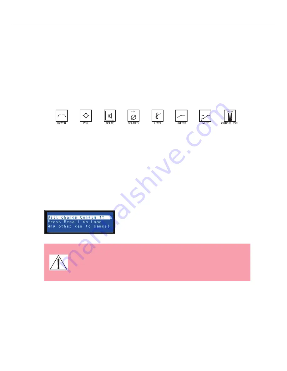
Each output employs two X-Over filters that can be assigned to a variety of filter types and slopes. Each
output channel provides 5 additional filters which can be used as parametric EQs, Low- / High-shelving
filters, or Lo-Pass and Hi-Pass filters, and also as All-Pass filters. In addition to a gain control for adjusting
the output level and a polarity switch, each output is monitored by a digital limiter with adjustable threshold,
attack and release.

List and Detailed Description

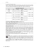
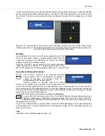
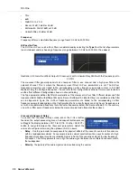
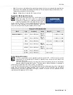
2  Way  Stereo  +  FR

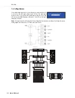
3  Way  Stereo

4  Way  +  FR

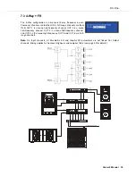
5  Way  +  FR

Free Configuration - Full Edit 2 in 6 Out

3 Way Stereo - Mono Sub + FR

4 Way Stereo - Mono Sub + LF

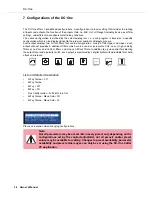
Please use caution when changing configurations.

Note: 

Not all parameters may be accessible in every preset and, depending on the
configurations set by the contractor/installer, not all presets and/or preset
values may be available for editing. Changes to preset availability, parameter
availability and preset value ranges can only be set using the DC-One Editor
PC application.

Summary of Contents for DC-One

Page 1: ...OWNER S MANUAL BEDIENUNGSANLEITUNG Delay GEQ PEQ Level Delay PEQ HPF X Over Recall Store Edit Setup Mute Mute Mute Mute Mute Mute Electro Voice DC One Program U01 FullEdit 2in 6out...

Page 2: ...e 20 LCD Display 20 Input Level Meters 20 Output Level Meters 20 Output Gain Reduction Meters 21 Output Channel Mute Buttons 21 Output Channel Function Indicators 21 Preset Recall 21 Preset Store 22 E...

Page 3: ...68 Mute Tasten der Ausgangskan le 68 Funktionsanzeigen der Ausgangskan le 68 Presets aufrufen 68 Preset speichern 69 Editieren 70 Parameter 71 Setup 80 Setup Men s 80 DC One Konfigurationen 84 Stereo...

Page 4: ...o do so Refer all servicing to qualified service personnel 1 Security regulations as stated in the EN 60065 VDE 0860 IEC 65 and the CSA E65 94 have to be obeyed when servicing the appliance 2 Use of a...

Page 5: ...DC One Owner s Manual 5...

Page 6: ...DC One 6 Owner s Manual 1 Overview...

Page 7: ...DC One Owner s Manual 7...

Page 8: ...ems with a single Analog Devices SHARC DSP processor The substantial advantages of the DC One over discrete signal processing racks include 24 bit 48 kHz digital signal path No patch cables to fail or...

Page 9: ...t closure interface for recall of up to eight selectable presets Front panel USB port for connection to PC preset editing and real time parameter control and monito ring Firmware updates FLASH memory...

Page 10: ...mal signal to noise performance is obtained when the nominal average input level consistently lights the 3dBu green and or 6dBu Yellow LED indicators As the DC One is a digital audio device and digita...

Page 11: ...ssing the Edit button again compares the edited preset if parameters have been altered to the original un edited preset This compare function will audibly switch between the altered parameters and the...

Page 12: ...y to Run mode To exit without storing the current preset press the Edit or Setup buttons to return to the Run mode screen 12 Input HPF Button Pressing the HPF button places the current preset in Edit...

Page 13: ...on configuration 20 Output Level Meters Each output channel has an eight segment output level VU meter Meter response characteristics can be selected in the Setup menu Normal Fast Peak Hold Slow Deca...

Page 14: ...l may be identified as a sub low low mid mid mid hi hi or full range output One or two adjacent LED are displayed to indicate all possible output bandpasses Full range is indicated by no lit LED s 3 2...

Page 15: ...log audio inputs an AES EBU digital stereo input is provided and selectable in the Setup menu The input conforms to IEC standard 60958 Type I Connections must be made with three conductor 110 Ohm twis...

Page 16: ...provided by the rack ears must be secured Power Connection The DC One must be connected to A C power only by means of the provided IEC A C cable or by a power cable provided by the dealer installer t...

Page 17: ...A standard female to female RS 232 cable that conforms to the null modem wiring convention is used to connect the two units Cable length should be kept to less than 45 feet 15 m for the most reliable...

Page 18: ...reset Input Level Adjustment The final step in setting up installing and connecting the DC One is to set proper input levels to the unit The DC One does not itself have input level controls Proper inp...

Page 19: ...r Preset locations for later recall Editing can be performed from the front panel LCD display or on a PC with the DC One Editor Graphic User Interface Application Full editing is recommended only for...

Page 20: ...3 Output Level Meters Each output channel has an eight segment output level VU meter Meter response characteristics can be selected in the Setup menu Normal Fast Peak Hold or Slow Decay The yellow seg...

Page 21: ...ets and can store up to 20 user presets F01 F60 U01 U20 Factory presets have been designed to represent common system configurations utilizing Electro Voice loudspeaker systems User presets allow you...

Page 22: ...s and symbols Pressing and holding the Value Up and Down buttons will scroll rapidly through the character set Press the Select buttons to move to the next or previous character position When the pres...

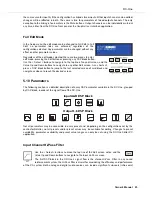
Page 23: ...s a short cut press a DSP block button to jump to the last selected screen of said block and navigate as above to reach the desired screen 5 10 Parameters The following section is a detailed descripti...

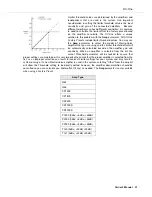
Page 24: ...frequencies below the selected cut off frequency good for acou stic music that is generally within known frequencies but may drop below without much energy 12dB Oct Steeper attenuation of frequencies...

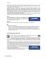
Page 25: ...smaller the range of adjacent frequencies that will be effected The gain parameter determines the amount of boost or cut that is applied to the frequencies that are affected by the filter Use the Sele...

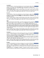
Page 26: ...layed on the top line of the LCD display To adjust the amount of boost or cut for a selected frequency band select the band with the Select buttons and press the Value Up or Down buttons as required T...

Page 27: ...cies that result in the efficient reproduction of the audio spectrum and a smooth sound The DC One crossover routes frequencies to the appropriate drivers to accurately reproduce sound The crossover n...

Page 28: ...n be bypassed Again the Hi Pass frequency parameters are linked to the corresponding Lo Pass frequency parameter depending on the Configuration that is currently being used High pass frequencies are s...

Page 29: ...the positioning of cabinets or speaker arrays relative to each other or the original sound source The Delay parameter determines the delay time of the corresponding channel or the distance between di...

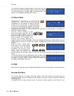
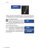
Page 30: ...nge the output channel Hold down the Level button for some seconds you will then be presented with the Limiter screen Use the SELECT key to navigate between Threshold 9 0 dBu to 21 0 dBu Release 50 0m...

Page 31: ...t will be automatically calculated based on the amplifier gain and sensitivity When an amplifier is selected from the list the actual Threshold parameter will be locked to ensure that proper settings...

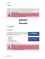
Page 32: ...E arrows to choose between 1 2 Way Stereo FR 2 3 Way Stereo 3 4 Way FR 4 5 Way FR 5 Free Configuration 6 3 Way Stereo Mono Sub FR 7 4 Way Stereo Mono Sub LR For more on Configuration Setup see page 36...

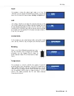
Page 33: ...o 10 LCD contrast Limiter Units In this window you can select between dBu and Volt for Limiter units Use the SELECT key to navigate to the UNITS parameter Metering Users can set their VU metering pref...

Page 34: ...ameters Any or all of the DC One s DSP Blocks and or individual parameters within the DSP blocks can be locked or hidden from this window by selecting the corresponding box to engage the lock icon For...

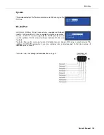
Page 35: ...aster Slave operation Use the SELECT key to navigate to the MODE parameter and use the up down VALUE arrows to choose between RS 232 and Contacts Contacts allow control messages to select individual p...

Page 36: ...al filters which can be used as parametric EQs Low High shelving filters or Lo Pass and Hi Pass filters and also as All Pass filters In addition to a gain control for adjusting the output level and a...

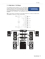
Page 37: ...el and IN B as the right input channel OUT 1 is the left Low frequency output and OUT 2 is the left High frequency output OUT 4 and OUT 5 are the corresponding right Low frequency and High frequency o...

Page 38: ...put channel and IN B as the right input channel OUTs 1 4 L R are the Sub frequency channel OUT 2 5 L R are Low and Mid frequency channels 3 6 L R are the High frequency channels Note On Input channels...

Page 39: ...T 1 is a mono Sub frequency channel OUT 2 is a mono Low frequency channel OUT 3 is a mono Mid frequency channel and OUT 4 is the mono High frequency OUT 5 and OUT 6 are Full range channels Note On Inp...

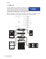
Page 40: ...frequency channel OUT 2 the mono Very Low frequency OUT 3 is the mono Low frequency channel OUT 4 is the mono Mid Frequency channel OUT 5 is the mono High frequency channel and OUT 6 is the Full rang...

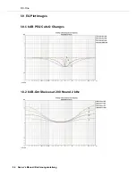
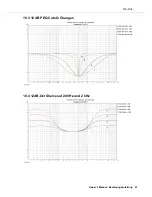
Page 41: ...DC One 96 Owner s Manual Bedienungsanleitung 10 EQ Plot Images 10 1 6 dB PEQ Cuts Q Changes 10 2 6 dB Oct Shelves at 200 Hz and 2 kHz...

Page 42: ...DC One Owner s Manual Bedienungsanleitung 97 10 3 12 dB PEQ Cuts Q Changes 10 4 12dB Oct Shelves at 200 Hz and 2 kHz...

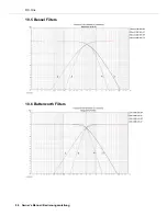
Page 43: ...DC One 98 Owner s Manual Bedienungsanleitung 10 5 Bessel Filters 10 6 Butterworth Filters...

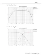
Page 44: ...DC One Owner s Manual Bedienungsanleitung 99 10 7 Hi Lo Pass Filters 10 8 Linkwitz Riley Filters...

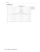
Page 45: ...DC One 100 Owner s Manual Bedienungsanleitung 10 9 PEQ Gains...

Page 46: ...DC One Owner s Manual Bedienungsanleitung 101...

Page 47: ...Notes...

Page 48: ...Notes...

Page 49: ...h Communications Systems Telex EVI Audio Shanghai Co Ltd Room 3105 3109 No 1 Building No 218 Tian Mu West Road Shanghai China Postal Code 200070 Phone 86 21 6317 2155 Fax 86 21 6317 3023 Germany Bosch...

Reviews: