Electro Industries/GaugeTech Shark 100 Quick Start Manual Download Page 4


Doc

#    

E145703   V.1.14     


             QS - 4

                      Shark® 100 Meter Quickstart

Electro 

Industries/GaugeTech

Powered by Innovation™
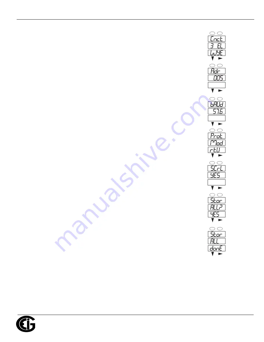
10.Press the 

ENTER 

button to go to the Connection setting screen (Cnct). The current 

     setting is shown in the second line. Press the 

DOWN ARROW

 to choose another 

     value. You can choose 3 EL (element) WYE, 2 Ct del (Delta), or 2.5 EL WYE.

11.Press the 

ENTER 

button to go to the meter Address setting screen (Adr). The 

     meter’s current address is shown in the second line. To change the setting, press 

     the 

DOWN


ARROW

 until the value you want is displayed. Then press the 

RIGHT 

     ARROW 

to move to the next digit. Repeat until the setting is done. Valid address-

     es are from 001 through 247. 

IMPORTANT! If you are using the Ethernet 

     option (INP10) 

do not change any settings - leave the address as 001.**

12.Press the 

ENTER 

button to go to the meter Baud Rate setting screen (bAUd). The 

     meter’s current Baud Rate is shown in the second line. Press the 

DOWN ARROW


     to choose another Baud Rate. You can choose 9600 (choose this for RS485 

     connection), 19.2 (19200), 38.4 (38400) or 57.6 (57600). 

IMPORTANT! If you 

     are using the Ethernet option, 

do not change any settings - leave the Baud Rate

     as 57.6.**

13.Press the 

ENTER 

button to go to the meter Protocol setting screen (Prot). The 

     meter’s current Protocol is shown in the second and third lines. Press the 

DOWN 

     ARROW

 to choose another communication Protocol. You can choose Mod rtU 

     (Modbus RTU; choose this for RS485 connection), Mod ASCI (Modbus ASCII), 

     or dnp (DNP 3.0). 

IMPORTANT! If you are using the Ethernet option, 

do not 

     change any settings - leave the protocol as Mod rtU.**

14.Press the 

ENTER 

button to go to the Scroll setting screen (SCrL). The current

     setting is shown in the second line. Press the 

DOWN ARROW

 to choose another

     setting. You can choose YES (the meter readings will scroll on the display) or no

     (the meter readings will not scroll on the display).

15.Press the 

MENU 

button twice. You will see the Store Settings screen (Stor ALL?)

     The default setting is YES. To save the settings you’ve made, press the 

ENTER


     button. You will see the confirmation screen (Stor ALL done) and then the meter 

     resets.


NOTE: 

If you do not want to save your settings, press the

 RIGHT ARROW. 

YES 

     changes to no. Press the

 ENTER 

button. 


**The Shark

®

 100 meter’s Ethernet communication settings are the default settings of 

Address 1, Baud Rate 57.6 and Protocol Mod rtU. See the 

Shark® 100/100T Meter Installation and 

Operation Manual

 (see page QS-1 for the download link) for additional configuration instructions for 

the Shark

®

 100 meter’s Ethernet port

A

B

C

-

-

-

MENU

ENTER

A

B

C

-

-

-

MENU

ENTER

A

B

C

-

-

-

MENU

ENTER

A

B

C

-

-

-

MENU

ENTER

A

B

C

-

-

-

MENU

ENTER

A

B

C

-

-

-

MENU

ENTER

A

B

C

-

-

-

MENU

ENTER

Summary of Contents for Shark 100

Page 1: ...uide gives basic installation wiring and programming instructions For additional meter oper ation and programming information refer to your meter s Installation and Operation Manual and the Communica torPQA and MeterManagerPQA Software EnergyPQA com AI Driven EMS User Manual on EIG s website User Manual https www electroind com products shark 100 power and energy meter transducer From the webpage ...

Page 2: ...Connection N L GND N Vref Va Vb Vc LINE LOAD CT Shorting Block FUSES 3 x 0 1A FUSE 3A C C B B A A N N lc HI LO lb HI LO la HI LO Earth Ground Earth Ground L Power Supply Connection N L GND N Vref Va Vb Vc LINE LOAD CT Shorting Block FUSES 3 x 0 1A FUSE 3A C C B B A A N N lc HI LO lb HI LO la HI LO Earth Ground Earth Ground L Power Supply Connection N L GND N Vref Va Vb Vc LINE LOAD CT Shorting Blo...

Page 3: ...creen CT S The current Scaling is shown in the second line Press the DOWN ARROW to choose another value You can choose 1 10 or 100 7 Press the ENTER button to go to the PT numerator setting screen Pt n The current PT numerator is shown in the second line To change the setting press the DOWN ARROW until the value you want is displayed Then press the RIGHT ARROW to move to the next digit Repeat unti...

Page 4: ...creen Prot The meter s current Protocol is shown in the second and third lines Press the DOWN ARROW to choose another communication Protocol You can choose Mod rtU Modbus RTU choose this for RS485 connection Mod ASCI Modbus ASCII or dnp DNP 3 0 IMPORTANT If you are using the Ethernet option do not change any settings leave the protocol as Mod rtU 14 Press the ENTER button to go to the Scroll setti...

Page 5: ...0345 Pt d value as 69 Pt S value as 1000 For additional programming instructions for the faceplate buttons see Chapter 6 in the Shark 100 100T Meter Installation and Operation Manual Connect to the Meter through the RS485 Port The Shark 100 meter has a stan dard RS485 port that makes connec tion between the meter and a laptop PC very simple The Shark 200 meter s RS485 port uses standard 2 wire hal...

Page 6: ... product rs485 to usb communication converter 2 Open CommunicatorPQA software see page QS 1 for the download link 3 Click Connect in the Icon Bar 4 You will see the Connect screen Make sure your settings match the ones shown on the right use pull down menus 5 Click Connect The Device Status screen confirms the connection Click OK to close the Device Status screen 6 Click the Profile button on the ...

Page 7: ...y Voltage in Full Scale NOT Ratios NOTE You can also enter the Ratios for CT PT Numerator and Denominator and click the Update CT Update PT buttons to let the software calculate the Numerator Denominator and Multiplier for you You can then empty the Ratio fields and click the Update Ratio buttons to confirm the calculated set tings you will see the same ratios you initially entered See Chapter 9 i...

Page 8: ...he Device Designation field Note that it is important to name each meter individu ally since the meter name is used to name the log databases when logs are downloaded See Chapter 9 in the software manual for an explanation of the other settings in this screen IMPORTANT When you have made changes to the meter s Device Profile click Load Profile at the bottom of the Device Pro file screen to send th...

Reviews: