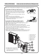
7.5M
7.5~
4
0M
1
2
3
6
5
4
1
2
3
4
5
6
1
2
3
4
LO HI
INSTALLATION MANUAL
4.4 System Evacuating
Length of
Evacuation Method
Charging quantity
Connection Tube
of refrigerant
B. Evacuation using self-provide cooling
agent of the installing worker
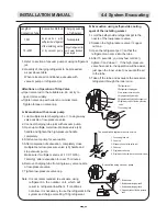
1. Joint the self-provide refrigerant pot to the
nozzle of the low-pressure valve.
2. Slacken the high-pressure valve
copper
nut cap.
3. Open the refrigerant pot
so that the
refrigerant can come into the tube.
4. After 15 seconds, you may feel cold at
,
tighten
and close
. If the high-pressure
valve has nozzle, the operation will be easier,
just open the inner valve to evacuate the air
in the tube.
5. Take off the tube and evacuate the excessive
refrigerant through the inner core.
E v a c u a t i o n w i t h
self-provide refrigerant
of the installing worker
or by vacuum pump.
Nameplate
(55g of refrigerant for
each meter of added
pipe length.)
1. Refer to section of vacuum pump or using refrigerant
jar.
2. Quantity of charging refrigerant to be proceeded
as per above table.
When relocate air conditioner, evacuate with
vacuum pump or refrigerant jar.
Open valve rod to the suitable are, do not try to
open it more widely.
Tighten valve cap with wrench or similar tools.
Tighten torque on valve cap.
1. Joint multiple meter charging tube
to single-way
valve nozzle of low-pressure valve.
2. Connect charging tube joint with vacuum pump.
3. Open up multiple meter low-pressure valve (L0)
handle and tighten the high-pressure handle
completely.
4. Start vacuum pump for evacuation.
5. After completion of evacuation, completely close
multiple meter low-pressure valve (L0) hardle and
stop vacuum pump.
Make sure if multiple meter is at -10 X 10 Pa (-
76cmHg) after evacuation for over 15 minutes.
6. Remove charging tube from single-way valve nozzle
of low-pressure valve.
7. Tighten low-pressure valve cap.
Note: It is not recommended to evacuate using
refrigerant in the outdoor unit, which will
result in refrigerant insuffient. If conditions
not allow, it is necessary to use the refrigerant in the
system and charge more 80g-100g refrigerant.
Attentions on Operation of Stop Valve
A. Evacuation with vacuum pump
5
1. Multiple meter
2. Multiple meter charging tube B
3. Multiple meter charging tube A
4. Single-way valve of the low-pressure
valve
1. Refrigerant pot
2. Refrigerant charging pipe
3. Low-pressure suction valve
4. High-pressure liquid valve
5. High-pressure liquid valve copper nut
6. Single-way valve of the low-pressure
valve
7. Connecting tube
The schematic diagram of suction valve
1. Connecting tube nut
2. Valve rod
3. Stopper (the set in the valve rod)
4. Valve cap
5. Single-way valve cap
6. Single-way valve rod (have valve core inside)
Evacuation using vacuum pump
Summary of Contents for FS 1200
Page 4: ...FS KFR 120L OU10 50 R407C Rev 01 Series FS Date 20 02 2004 ELECTRA CONSUMER PRODUCTS LTD...
Page 9: ...Model FS KFR 120L Rev 01 Series FS Date 20 02 2004 ELECTRA CONSUMER PRODUCTS LTD...
Page 12: ...Rev 01 Series FS Date 20 02 2004 ELECTRA CONSUMER PRODUCTS LTD...
Page 13: ...FM FM 1 2 AUTO C AM Free Standing Air Conditioner Operation Instructions Installation Manual...
Page 53: ...Part No 452809000 01...
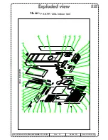
Page 54: ...Model FS KFR 120L Indoor Unit Rev 01 Series FS Date 20 02 2004 ELECTRA CONSUMER PRODUCTS LTD...
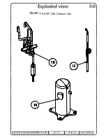
Page 56: ...Model FS KFR 120L Outdoor Unit Rev 01 Series FS Date 20 02 2004 ELECTRA CONSUMER PRODUCTS LTD...
Page 57: ...Model FS KFR 120L Outdoor Unit Rev 01 Series FS Date 20 02 2004 ELECTRA CONSUMER PRODUCTS LTD...
Page 58: ...Model FS KFR 120L Outdoor Unit Rev 01 Series FS Date 20 02 2004 ELECTRA CONSUMER PRODUCTS LTD...


