background image

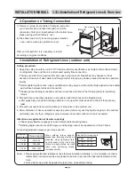
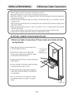
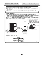
Dismantle front lateral board

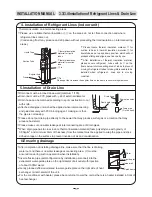
Open up outdoor wire-cross hole and put on square wire-cross diagram.
Induce connection wire out from 6 bit wiring board on outdoor unit, drill through outdoor wire-cross hole
and indoor wire-cross hole, and connect the wire to the 6 bit wiring board on indoor unit. Please refer to

the following diagram for power line wiring.

Secure lines with fixation clamps after wiring as the diagram.

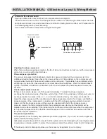
Signal connection

line on outdoor unit

Signal connection line

Checking the phase sequence:

Phase sequence protection:

How to adjust phase sequence:

The pressure protection:

When there is phase sequence protection, the fan of indoor and outdoor unit will run, but the compressor
will not run, or will run with abnormal noise.

The product is equipped with antiphase protector to make sure that when the compressor is in the
antiphase situation (below three phase), the power will be cut off immediately, so the compressor will
not work while the motor of indoor and outdoor unit can still work. The protector has an indicator, which
will light up only when the phase sequence is correct and without antiphase. When the indicator doesn't

light up, it indicates accidents to be handled. Refer to how to adjust the phase sequence to solve the

accident.

If there is an accident, please cut off the power immediately. To adjust the phase sequence
exchange the random two poles of the three external line L1/L2/L3 on wiring layout of the power wire, or
exchange random two poles of line 2

4

6 on the AV contactor directly. Two steps are needed to

adjust the phase sequence of the conditioner with phase sequence protector: first, make sure that the
phase sequence of the compressor is consistent with that of the phase sequence protector; second,
make sure that the phase sequence of the power is consistent with that of the phase sequence
protector. Usually, the first is adjusted before the conditioner leaves factory, but the latter must be
adjusted on site when installing. If the indicator lights and there is abnormal noise when the compressor
is in operation, please make sure that the phase sequence of the compressor is consistent with that of
the phase sequence protector.

Some products of our company have pressure protection equipment. If your unit has such equipment,
please read the following content:
High-pressure protection switch: to assure that the system will not be damaged by the overhigh pressure.
Low-pressure protection switch: to protect the compressor when the system is badly short of refrigerate.

If the above product is damaged, please use the accessory designated by our company.

INSTALLATION MANUAL 4.5Electrical Layout & Wiring Method

L

1

L

2

L

3

N

Red Black Brown Blue Yellow Green

Power lines on outdoor unit

Summary of Contents for FS 1200

Page 1: ...Technical Service Manual REFRIGERANT Rev Date SERIES FS KFR120L Free Standing R407C HEAT PUMP 01 29 02 04 Rev 01 Series FS Date 20 02 2004 ELECTRA CONSUMER PRODUCTS LTD FM FM 1 2 AUTO C AM...

Page 2: ...Package dimensions 4 units Units per palet 1 units Height stacking R 407C Refrigerant control SCROLL HR61YAB LG Compressor type model AXIAL X 2 Fan type qty 1125 RPM Fan speed HI 4200 2470 m hr CFM Ai...

Page 3: ...F WB Refrigerant tubing length one way 7 5m 24 6 ft 2 Guaranteed operating range Indoor Outdoor Upper limit 32 C DB 23 C WB 46 C DB Cooling Lower limit 21 C DB 15 C WB 21 C DB Upper limit 27 C DB 24...

Page 4: ...FS KFR 120L OU10 50 R407C Rev 01 Series FS Date 20 02 2004 ELECTRA CONSUMER PRODUCTS LTD...

Page 5: ...45 Outdoor Temp C DB CAPACITY W 30 C DB 50 RH 26 C DB 50 RH 23 C DB 50 RH Indoor Temp FS1200T R407c HEATING CAPACITY 6 000 8 500 11 000 13 500 16 000 18 500 21 000 10 5 0 5 10 15 Outdoor Temp C DB CA...

Page 6: ...utdoor Temp C DB TOTAL INPUT W 30 C DB 50 RH 26 C DB 50 RH 23 C WB 50 RH Indoor Temp FS1200T R407c HEATING TOTAL INPUT 2 500 3 000 3 500 4 000 4 500 5 000 5 500 6 000 6 500 10 5 0 5 10 15 Outdoor Temp...

Page 7: ...CHARGE PRESSURE Bar g 30 C DB 50 RH 26 C DB 50 RH 23 C DB 50 RH Indoor Temp FS1200T R407c HEATING SUCTION PRESSURE 1 50 2 00 2 50 3 00 3 50 4 00 4 50 5 00 10 5 0 5 10 15 Outdoor Temp C DB SUCTION PRES...

Page 8: ...ION PRESSURE Bar g 30 C DB 50 RH 26 C DB 50 RH 23 C DB 50 RH Indoor Temp FS1200T R407cHEATING DISCHARGE PRESSURE 14 15 16 17 18 19 20 21 22 23 24 10 5 0 5 10 15 Outdoor Temp C DB DISCHARGE PRESSURE Ba...

Page 9: ...Model FS KFR 120L Rev 01 Series FS Date 20 02 2004 ELECTRA CONSUMER PRODUCTS LTD...

Page 10: ...HEAT PUMP MODELS SERIES FS KFR 120L Rev 01 Series FS Date 20 02 2004 ELECTRA CONSUMER PRODUCTS LTD...

Page 11: ...e Nut 7 Unit Back Side 8 Copper Tube When the outdoor unit is installed above the indoor unit an oil trap is required every 5m along the suction line at the lowest point of the riser In case the indoo...

Page 12: ...Rev 01 Series FS Date 20 02 2004 ELECTRA CONSUMER PRODUCTS LTD...

Page 13: ...FM FM 1 2 AUTO C AM Free Standing Air Conditioner Operation Instructions Installation Manual...

Page 14: ...cting Sleep Function Timer Function Operation Modes for Timer Function Air Direction Control Turning Off Lock Function Protection Modes and Instructions for Service Electric Heater Maintenance and Car...

Page 15: ...ndoor Unit Installation 3 3 Refrigerant Line Installation 3 4 Drain Line Installation 3 5 Electrical Cable Connections 4 Outdoor Unit Installation 4 1 Selecting Location for Outdoor Unit Installation...

Page 16: ...be grounded to protect against electrical shock Installation of the air conditioner must be performed by an experienced air conditioning installer observing good refrigeration practice Electrical conn...

Page 17: ...FM FM 1 2 AUTO C AM Indoor Unit Air Out Air Outlet Outdoor Unit Air In Control Panel Air Out Air Out Air In Drain Tube Interconnecting Lines Air Inlet SYSTEM DESCRIPTION...

Page 18: ...quate temperature This HOT KEEP feature prevents uncomfortable cold air drafts Use of AUTO FAN is therefore recommended when the air conditioner is in HEATING mode Real time control and display automa...

Page 19: ...retains the last data entry whether or not the unit is plugged in Therefore when the unit restarts after a power distruption or failure it will resume operating in the same mode as before the power w...

Page 20: ...orking Pressing the button to increase the set room temperature When pressing the button to set operation time longer or shorter by pressing L button M Reset Button N V Power Switch Button and Indicat...

Page 21: ...ational Principle Chart for Free Standing Room Air Conditioner with Heat Pump Operational Principle Chart for Free Standing Cooling Only Room Air Conditioner Both outdoor unit and indoor unit start op...

Page 22: ...the last set mode Select the ventilating mode by pressing F mode selection button Select desired fan speed by pressing B fan speed button Different fan speed will be displayed on display panel after...

Page 23: ...will automatically switch to a lower airflow to maintain the selected temperature Heating operation with auto fan mode will automatically provide you a cold air preventive function The fan will be tur...

Page 24: ...of Saturday T2wk timing of Sunday T1 and T2 are two everyday timings representing different time periods Such time period will be repeated everyday T1wk and T2wk are the timing of the weekend The tim...

Page 25: ...to adjust start time of operation D Press SET button L again to activate timing start function OFF will appear E Repeat step c to set the closedown time F Press SET button L to activate timing closed...

Page 26: ...ff the air conditioner Indicator V on the air conditioner will be turned off Indicator A may stay lit indicating that the air conditioner is in stand by mode Press Lock button T to lock the last opera...

Page 27: ...t with heat pump Condenser overheating Stops compressor automatically when approaching over heating temperature Resumes operation automatically Heating Low outdoor temperature Condenser freezing up Re...

Page 28: ...t blocked One of the reasons to cause poor performance of the unit Cleaning Air Filter Whether or not to clean the air filter depends on the instruction of the filter indicator Steps of removing the f...

Page 29: ...vertical downward direction Keep room temperature evenly through adjusting vertical air blades During prolonged operation ventilate the room by opening windows After power failure microprocessor will...

Page 30: ...air conditioner Do not put any obstacles in the outlets of indoor unit or outdoor unit There may have buzz when air conditioner is in operation or just turned off which is produced by refrigerant cir...

Page 31: ...hock and injuries may be caused Avoid using iron strings in place of fuse Or breakdown may be caused or occurrence of fire disaster Avoid inserting sticks and other objects into suction entrance and b...

Page 32: ...r temperature setting Unit capacity is insufficient for load or room size Reset temperature Consult service center Filter indicator lights up Air filter needs to be cleaned Clean filter and reinstall...

Page 33: ...TO C AM 600 370 1900 INSTALLATION MANUAL 1 Outline dimensions for indoor outdoor unit OUTLINE DIMENSIONS FS 1200 INDOOR UNIT FC 1200 OUTDOOR UNIT OU 10 RC 900 340 246 461 950 970 97 705 69 50 492 573...

Page 34: ...nstallation Installation of indoor unit Installation of Refrigerant Lines Installation of Drain Line Electrical Connections Selecting Location for Installation Installation of Outdoor unit Installatio...

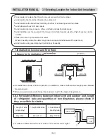
Page 35: ...arm may produce wrong actions because of the warm air Avoid location using special sprayer sulfur type frequently 1 Installed on leveled and firm floor 2 Space for installation and service Unit mm Min...

Page 36: ...Loose tap bolt 2 and remove please reverse the frontback of iron piece preventing dumping aligning one side with adaptable dimensions to wall surface and proceeding mounting on the other side tap bolt...

Page 37: ...re locally When installing air outlet tube on the ceiling of the unit please do not cap the clamp on the ceiling outlet on the unit and bolt hole for installation of air outlet tube e g keep long side...

Page 38: ...kg m3 and over 9 mm of thickness purchased from the market INDOOR UNIT 1 Location of Refrigerant Lines and Drain Line Push out hole for floor mounting 4 10 Hole Push out hole for bottom connection Pus...

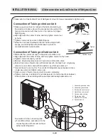
Page 39: ...and refer to the following table for tightening torque 2 Proceed flare connecting operation in succession and interconnect all refrigerant lines After pipes being connected leakage detector or soup wa...

Page 40: ...ipe union shall be applied when interconnecting and glued securely with PVC binding agent making sure that the pipe is not leaking Please do not put drain pipe directly to the sewer that may produce s...

Page 41: ...erconnections must be proceeded according to terminal code Compressor is inoperative when interconnection of power lines is wrong ELECTRIC CONNECTION ON INDOOR UNIT 1 Electrical Cable Connections Plea...

Page 42: ...ver Comb Liquid tube Suction tube Wiring Line on Indoor Unit Wiring Line on Outdoor Unit Brown Blue Red Yellow Green 2 For the heat pump unit power line and signal line connection must be proceeded De...

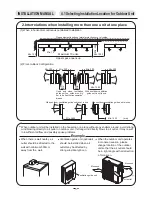
Page 43: ...ACES NECESSARY FOR OUTDOOR UNIT 1 Detailed distances of surrounding spaces necessary for separate setup 4 When obstructions at front and backside 5 When there are obstructions at four lateral sides up...

Page 44: ...ed on the housetop or a place without any shelters around avoid strong wind blowing directly to air outlet on outdoor unit If strong wind directly blows to air outlet it may result in insufficient air...

Page 45: ...nit Before securing the shock absorption block rubber accompanying the unit must be placed between the sole and the installation plane Foundation bolts for securing are purchased locally In order not...

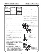
Page 46: ...ingle way valve caps on liquid valve and suction valve Screw down core of liquid valve with socket wrench and push out single way valve core on suction valve with screwdriver by which gas vents out Ga...

Page 47: ...ltiple meter charging tube to single way valve nozzle of low pressure valve 2 Connect charging tube joint with vacuum pump 3 Open up multiple meter low pressure valve L0 handle and tighten the high pr...

Page 48: ...ectrical Wiring Power supply for indoor unit Wiring qty Section area mm 2 Power supply for outdoor unit Wiring qty 5 Section area mm 2 2 5 Dimensions for earth connection wire mm 2 2 5 Wiring section...

Page 49: ...e is an accident please cut off the power immediately To adjust the phase sequence exchange the random two poles of the three external line L1 L2 L3 on wiring layout of the power wire or exchange rand...

Page 50: ...king indoor unit a When in operation mode whether or not the motor is running when fan is rotating whether or not there is abnormal noise b Whether or not the connection of drain lines is firm and is...

Page 51: ...r unit and defrost water produced when defrost can be drained out to the suitable place through drain line Installation method Insert the outdoor drain coupling into the 25 hole on base plate as per f...

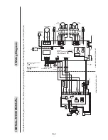
Page 52: ...C S L3 R 1 2 3 N HEAT N FAN MOTOR1 CAP1 AT OCT IN IMPRTANT EBFOR CONNECTING THE FH CUT THE WIRE BETWEEN 2 TABs FHCONTACTES 3PHRELAY BLK CH BLK L3 L2 L N COMP R V O F F S C OPTIONAL DNG 8 9 OCT OUT 8 9...

Page 53: ...Part No 452809000 01...

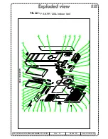
Page 54: ...Model FS KFR 120L Indoor Unit Rev 01 Series FS Date 20 02 2004 ELECTRA CONSUMER PRODUCTS LTD...

Page 55: ...p 24 45 780 copper tube protect plate down 25 45 7799 L R strengthen plate 2 26 45 7803 wire fixed plate 27 45 7797 back plate paint assy 28 45 8050 right side plate paint assy 29 45 8073 fix plate pa...

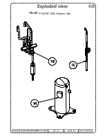
Page 56: ...Model FS KFR 120L Outdoor Unit Rev 01 Series FS Date 20 02 2004 ELECTRA CONSUMER PRODUCTS LTD...

Page 57: ...Model FS KFR 120L Outdoor Unit Rev 01 Series FS Date 20 02 2004 ELECTRA CONSUMER PRODUCTS LTD...

Page 58: ...Model FS KFR 120L Outdoor Unit Rev 01 Series FS Date 20 02 2004 ELECTRA CONSUMER PRODUCTS LTD...
Page 59: ...13 436357 SMALL ELECTRICAL COVER OU 1 3 14 439767 COMPRESSOR HR061YAA 1 1 15 439746 CAPILLARY ASSY OU10 50 R407C 1 1 16 439829 TUBING ASSY OU10 50 R407C 1 1 17 402494 BOARD TPHN 3C 1 1 18 442378 CAPA...

Reviews: