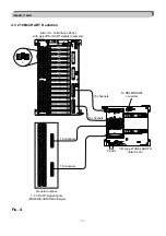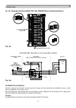
- 25 -
12. A
PPENDIX
A: M
UX
2700 I
SOLATION
S
TRUCTURE
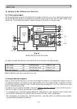
12.1 Three-port isolation
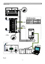
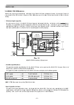
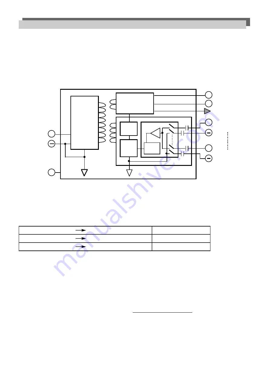
The three-port isolation structure of the MUX 2700 is depicted in Fig.8. As you can see, both the 24V supply input
and the RS-485 serial interface are isolated from the HART section, that is to say, from the HART signals on the
field devices. This is full galvanic isolation, implemented either by transformer or by optocoupler.
The galvanic isolation specifications for the MUX 2700 are summarised in the following table:
MUX 2700 G
ALVANIC
I
SOLATION
S
PECIFICATIONS
12.2 Input-channels isolation
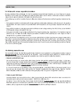
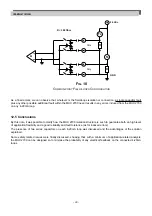
When you look at the field channels, you can see that full galvanic isolation is not implemented. Instead, a series of
non-polarised capacitors are inserted on each external interface line. The purpose of these capacitors is to block
the DC signal component present on each 4-20mA external loop, avoiding both a DC error induced on the loop
and any undesirable ground-loop.
The presence of a non-polarised capacitor in series with both the + and the – terminal of each channel is very con-
venient for a variety of reasons, as summarised in the following:
• It is possible to sense the HART signal at different DC voltage levels on each channel, as often required when
the same MUX interfaces both Transmitters and I/P devices or in other “mixed” configurations.
• It is not mandatory, to connected the + MUX terminal to the + side of the 4-20 mA current loop (in fact, the MUX
input terminals are basically not polarised).
IM-ENG-116/GB
POWER
SUPPLY
UNIT
+
24V
RS-485
INTERFACE
OPTO
ISOL.
CPU
MUX
A
HART
MODEM
+
+
A1
A3
SCREEN
A4,A5,A6
A31
A
A30
B
A32
2.2µF
0.68µF
2.2µF
0.68µF
C32
B32
C1
B1
CH1
CH32
F
IG
. 8
MUX 2700 I
SOLATION
S
TRUCTURE
24V supply
Field channels
1400 Vac, rms
24V supply
RS-485 serial port
1400 Vac, rms
RS-485 serial port
Field channels
500 Vac, rms

