- 27 -
12.3 Galvanic versus capacitive isolation
Having understood the advantages of a full, non-polarised capacitor-based isolation, you must however be aware
that this is not the same as a full galvanic isolation implemented on each channel, which was avoided on the MUX
design due to space constraints and higher manufacturing costs.
In the following, we will try to outline the main differences between the Galvanic and the Capacitive isolation techni-
ques:
• Full, galvanic isolation is associated with clearly specified, solid isolation distances, with reference to the applica-
ble standards. For space reasons, the selected MUX 2700 capacitors are not generally compliant with this requi-
rement.
• Full, galvanic isolation is generally requested to withstand a test voltage starting from 500 Vdc up, while the MUX
2700 capacitor rating is around 60 Vdc only.
• Full, galvanic isolation is generally specified with the lowest possible stray capacitance. For functional reasons
(that is to say, to enable the HART frequency acquisition) the MUX 2700 capacitors are much higher of what is
usually found in a galvanic isolated solution.
Due to the previous considerations, when you connect a MUX2700 to 4-20mA loops that are galvanic isolated from
each other, you loose the full galvanic isolation among the channels. On the other hand , you still have a relevant
advantage with respect to a solution that simply connects the channels with a common point, because you still
have full DC isolation up to the specified voltage and you don’t need to worry about possible ground-loop induced
errors on the 4-20mA signals.
12.4 Safety-related issues
It is important to stress the fact that capacitor-based isolation is not equivalent to a full galvanic isolation, however
this does not mean that the MUX 2700 can be expected, under reasonable fault conditions, to interfere with the
connected 4-20 mA loops. A few application examples can in fact be useful to clarify the situation.
• Galvanic isolated field loops
Let us assume that you connect with 4-20mA loops that are fully galvanic isolated from each other. In this case,
it can be shown that a single shorted input capacitor on each channel, plus any possible additional MUX fault
(apart from shorted input capacitors) does never result in any interference on the 4-20mA loops. In addition, with
a single shorted capacitor on each channel the MUX is still fully functional.
In a more formal term, the probability of any “electrical feedback” of the MUX 2700 on the loops signals is very
low, and you can consider the control system for “fail-safe” applications (this doesn’t mean, however, that the
MUX is fail-safe certified or that it will keep working properly when in a generic “single-fault” condition).
• Common-point field loops
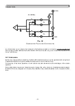
A similar situation can be found when the 4-20mA loops which the MUX 2700 connects to share a common Vdc
connection point, with a current sense resistor < 300 Ohm to GND (Fig. 10) .
As before, it can in fact be shown that a single shorted capacitor on each channel, plus any possible additional
MUX fault (apart from shorted input capacitors) does never result in any interference on the 4/20 mA loops. In
addition, with a single shorted capacitor on each channel the MUX is still fully functional.
IM-ENG-116/GB

