background image

17

en

11 MEASUREMENT - RECORDING YOUR READINGS

Your gauge is equipped with a data logger - an essential feature for improving the efficiency of
product inspection. With a data file open, all your readings values are saved into the file, therefore
eliminating the need to manually record measurements during the inspection process. Once all the
measurements have been taken, the gauge can then be connected to a computer or serial printer
to save and print the results of the inspection.

11.1 ABOUT THE DATA LOGGER

With a data file open, as you take measurements, the measurement data is stored in files in the
gauge memory.

Data logger file format: 

You have a choice of two different file formats:

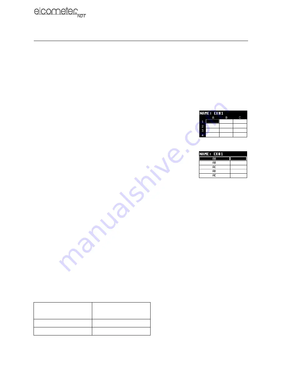
Grid format

: Similar to a spreadsheet format in which each cell is used 

to store a reading. Cells are referenced by the row number (1 to 999) 
and the column label (A to ZZ).

Sequential format

: A single column of up to 512 possible rows (read-

ings), and a column of corresponding identifiers associated with each 
individual reading. The identifier can be a combination of up to 10 
alphanumeric/special characters (see below), however it must not 
start or end with a special character. Once a start and end ID are 
entered into the gauge and the log created, the gauge automatically 
generates all the identifiers within that range.

Data logger filename character sets: 

Any combination of the following characters can be used

for file names and sequential format identifiers:

Numeric characters: 0 - 9

Alpha Characters: A - Z

Special Characters: ! ' _ # space / . - ( )

What measurement data is saved: 

When a measurement is taken (irrespective of log file format),

the following information is saved:

The reading value.

A screenshot of the echo waveform plus all the gauge settings. This ‘Save Graphics’ option 
can be toggled on/off. 

Memory capacity: 

You can create and save as many data files as required up to the maximum

capacity of the gauge memory (32 Mbit). If you try to create a new file which exceeds the memory
capacity, the gauge will display an error message. In this instance, to free some space in memory,
you should consider deleting some of the existing files or transferring them to a computer

Note: Multiple grids can be created and saved as template files on a PC, using NDT Link software,
but only one grid can be uploaded into the gauge at a time.

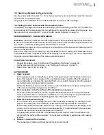
Save Graphics Option

Memory Capacity 

(readings)

On

16 000 +

Off

210 000 +

Grid format

Sequential format

Summary of Contents for UG20DL

Page 1: ...0 en Model UG20DL Underwater Thickness Gauge Operating Instructions...

Page 2: ...y network which supplies buildings used for domestic purposes These operating instructions are available for download on our website www elcometerndt com The following trademark is a registered tradem...

Page 3: ...adings 14 9 ThruPaint Measurement Technique 15 10 Measurement Options 15 11 Measurement Recording your Readings 17 12 Data Transfer Software 19 13 Storage 20 14 Maintenance 21 15 Technical Specificati...

Page 4: ...being measured The Model UG20DL includes a data logging memory facility which allows readings to be stored in the memory before being downloaded to a computer 1 1 STANDARDS Your gauge can be used in a...

Page 5: ...HOUSING SEALS The housing is sealed by o rings one on each end cap which require meticulous care In order to maintain a watertight seal the o rings and their mating surfaces must be clean free of fore...

Page 6: ...eries from the gauge if it is to remain unused for a long period of time This will prevent damage to the gauge in the event of malfunction of the batteries 3 2 CHOOSING THE TRANSDUCER When you purchas...

Page 7: ...he sound echoes back into the transducer When the transducer is placed against the material being measured it is the area directly beneath the centre of the wearface that is being measured 3 4 SWITCHI...

Page 8: ...itted to the gauge dual element type or single element membrane type Method Action Notes Press and Short Hold Enters into or exits out of the menu struc ture If entering into the menu structure Enter...

Page 9: ...n it is switched on and then every 30 seconds This provides visual confirmation of the the settings at any time without having to scroll through the menus to find the values of the settings The gauge...

Page 10: ...measured until a new measurement is made Note When the battery voltage is low the entire display will begin to flash When this occurs the batteries should be replaced 6 MEASUREMENT MODES Your gauge ha...

Page 11: ...HO ECHO MODE E E THRUPAINT This mode measures between two reflections This technique is commonly used to eliminate errors from surface coatings and also to make measurements in multiple layered materi...

Page 12: ...not set correctly all of the measurements the gauge makes will be in error by some fixed number When the zero point of the transducer is set this fixed error value is measured and automatically correc...

Page 13: ...the current velocity setting in your gauge Disregard the value displayed it is not important What is important is accurately performing these steps to ensure reliability of the zero calculation 4 Use...

Page 14: ...transducer from the zero disk 7 4 CALIBRATING In order for the gauge to make accurate measurements it must be calibrated to the sound velocity of the material being measured Different types of materia...

Page 15: ...the Gauge on page 11 Select units see Units on page 16 8 2 PROCEDURE 1 Apply couplant For the gauge to work correctly there must be no air gap between the transducer and the sur face of the material t...

Page 16: ...detection mode The combination of using both modes is ideal for the advanced inspectors needs 9 2 Setting Up ThruPaint Mode When you select the appropriate transducer type from the list of probes stor...

Page 17: ...trying to measure a material that is hard to penetrate due to the material type or the overall thickness of the material and when locating fine pits or flaws In these instances increase the gain to s...

Page 18: ...ow however it must not start or end with a special character Once a start and end ID are entered into the gauge and the log created the gauge automatically generates all the identifiers within that ra...

Page 19: ...at is larger than the stated boundaries an error message OUT OF MEMORY is displayed 11 2 2 Auto Increment Direction The Auto Increment function allows you to specify which direction to advance the cur...

Page 20: ...g see Measurement Taking Readings on page 14 4 Press and release the control button The measurement value and data is saved to the current storage location of the data file The storage location is the...

Page 21: ...ires an available communications port in order to transfer data to and from the gauge NDT Link supports COM1 COM2 COM3 and COM4 12 1 3 USB to Serial Converter Some newer laptop computers do not have s...

Page 22: ...l Elcometer NDT supplier or directly to Elcometer NDT The warranty will be invalidated if the instrument has been opened 14 2 TRANSDUCER The transducer will wear with repeated use Transducer life depe...

Page 23: ...styrene polyurethane PVC stainless steel and steel Weight including batteries 680 g 1 5 lbs Dimensions Length x Dia 229 mm x 60 33 mm 9 0 x 2 375 Gauge Operating Temperature 29 C to 60 C 20 F to 140 F...

Page 24: ...e limitation or exclusion may not apply to you However any implied warranty of merchantability or fitness is limited to the two year duration of this written warranty This warranty gives you specific...

Page 25: ...ing measured such that a strong stable echo is received by the gauge Several factors affect the strength of ultrasound as it travels These are outlined below 18 1 INITIAL SIGNAL STRENGTH The stronger...

Page 26: ...High penetration plastics and castings PULSE ECHO P E COATING OFF Cast iron 1MHz to 5MHz transducer Cast aluminium 10MHz transducer Plastics typically require lower frequency trans ducers depending o...

Page 27: ...acts on light the beam becomes diffused and scattered in all directions In addition to posing obstacles to measurement rough surfaces contribute to excessive wear of the transducer particularly in sit...

Page 28: ...e material decreases In most applications with surface temperatures less than approximately 100 C 200 F no special procedures are required At temperatures above 100 C 200 F the change in sound velocit...

Page 29: ...5232 0 206 PVC 2388 0 094 Copper 4674 0 184 Quartz Glass 5639 0 222 Epoxy Resin 2540 0 100 Approx Rubber Vulcan ised 2311 0 091 German Silver 4750 0 187 Silver 3607 0 142 Glass Crown 5664 0 223 Steel...

Page 30: ...the STORE top level menu item is replaced by MEMOFF DIRECT NORTH Part of the data logger The submenu item selected specifies in which direction to advance the cursor after a measurement is stored If a...

Page 31: ...ers of the same type frequency and diameter your gauge has a zero coating feature This enables your gauge to obtain very accurate readings on coatings eliminating potential errors incurred from slight...

Page 32: ...or measurements in millimetres MODE P E Select to measure non coated material bare metals PECT Select to measure coated materials Measures the thickness of both the base material and coating E E Selec...

Reviews: