16
en
Spike:
The Spike option is used for high resolution and general applications and can be considered
as the standard setting.
Thin:
When additional energy is needed for more penetration, the Thin option may be necessary.
Wide:
When even more energy is needed for more penetration, the Wide option may be necessary.
High frequency applications, where resolution is a requirement, may require the Spike or Thin
settings to achieve optimal results. Low frequency applications, where more penetration is a
requirement, may require the Thin or Wide settings, offering increased penetration. The variety of
transducer frequencies and diameters used in conjunction with the pulse width setting, enable you
to fine tune the gauge to your application needs.
To adjust the Pulse setting:
Select MENU/PROBE/PULSE
12 FLAW MODE
(CG70ABDL only)
12.1 INTRODUCTION
Your gauge includes a basic flaw prove up mode. Further information on flaw detection can be
found on the Elcometer NDT Knowledge Centre on www.elcometerndt.com.
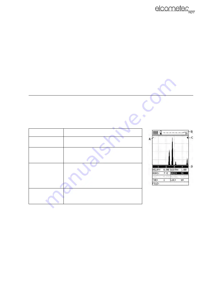
12.2 FLAW MODE VIEW
12.3 ENABLING FLAW MODE
To use Flaw Mode, an angle beam transducer and dual lemo to single microdot cable are required.
These are available from Elcometer NDT.
1.
Attach the dual lemo to microdot cable and angle beam transducer to the gauge.
2.
Select MENU/PROBE/FLAW MODE
3.
Use the LEFT and RIGHT arrows to adjust the value of the FLAW MODE function (OFF, ON,
PEAK):
•
OFF - Disables Flaw Mode
•
ON - Enables Flaw Mode
Feature
Description
A
Horizontal gridlines on the display represent
increments of 25% of the full screen height
B
The thickness reading normally occupying
this space is not relevant to flaw detection. It
is replaced by a dashed line
C
The peak hold symbol is only visible when
flaw mode is set to peak. Indicates the high-
est amplitude reflection detected during a
scan. Pressing CLR will reset the position of
the peak hold symbol to zero
D
Vertical gridlines on the labelled with quad-
rant numbers. Unlike thickness mode they do
not correspond to the material thickness


