elco Thision EVO WH 250-120 Operation And Installation Manual Download Page 7

4

3

1

2

11
6
7

9

8

10

5

16

12

18

17

14

13

15

Construc  on

GB

7

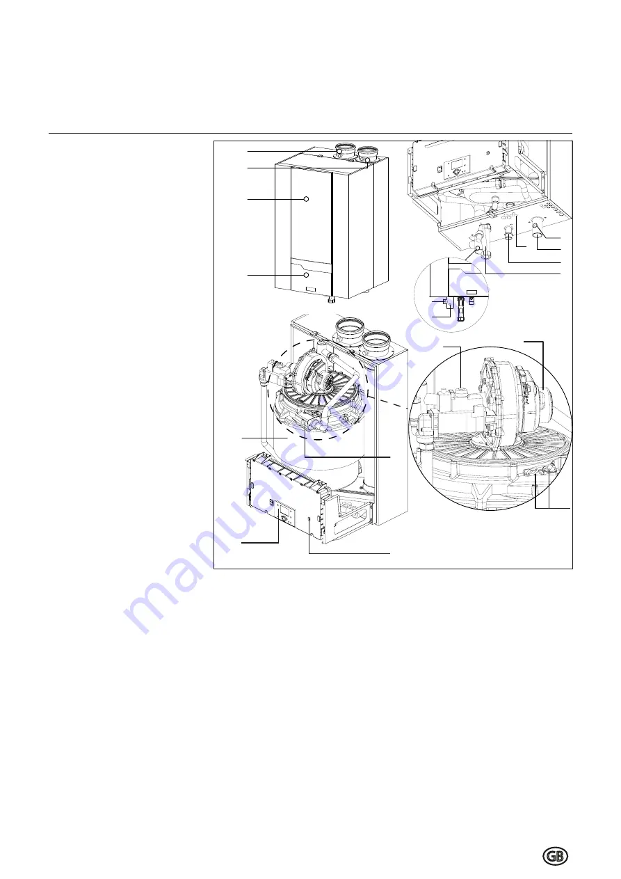
Layout of the boiler
Opera  ng principle

Layout of boiler

The THISION L EVO boiler consists of 
the following main components:

1. Casing
2. Access door to control panel
3. Flue gas connec  on

(+ test point)

4. Air intake connec  on

(+ test point)

5. Flow water connec  on
6. Return water connec  on
7. Gas connec  on
8. Syphon
9. Input for wiring
10. Connec  on for safety valve
11. Connec  on for 

fi

 ll/drain valve

12. Control Panel
13. Fan
14. Gas valve
15. Igni  on and ionisa  on electrodes
16. Heat exchanger
17. Igni  on transformer
18. Electrical input connec  ons

Opera  ng principle

The THISION L EVO is a fully modu-
la  ng boiler.
The control unit of the boiler adapts 
the modula  on  ra  o  automa  cally 
to the heat demand requested by 
the system. This is done by control-
ling the speed of the fan. As a re-
sult, the venturi mixing system will 
adapt the gas ra  o to the chosen fan 
speed, in order to maintain the best 
possible combus  on 

fi

 gures  and 

therewith the best e

  ciency.

The 

fl

 ue gases created by the com-

bus  on are transported downwards 

through the heat exchanger and 
leave the boiler at the top into the 
chimney connec  on.
The return water from the system 
enters the boiler in the lower sec-

 on, where is the lowest 

fl

 ue  gas 

temperature in the boiler. 
In this sec  on  condensa  on  takes 
place. The water is being transport-
ed upwards through the heat ex-
changer, in order to leave the boiler 
at the 

fl

 ow  connec  on. The cross 

fl

 ow working principle (water up, 

fl

 ue gas down) ensures the most ef-

fi

 cient combus  on results.

The LMS14 control unit can control 
the boiler opera  on based on:

• Boiler control

(stand alone opera  on);

• weather compensated opera  on

(with op  onal outdoor sensor);

• with 0-10V external in

fl

 uence (tem-

perature or capacity) from a build-
ing management system.

Summary of Contents for Thision EVO WH 250-120

Page 1: ...Operation and Installation manual THISION EVO WH 08 2016 PAG THEWH01...

Page 2: ......

Page 3: ...0 21 Gas tightness check 21 Water heater shut down 21 Maintenance Checklist 25 Replacing the electrodes 25 Cleaning the condensate receptacle 26 Cleaning and refilling the syphon 26 Inspection of the...

Page 4: ......

Page 5: ...directive 2004 108 EEC EMC directive EN 483 Gas fired central heating boilers Type C boilers of nominal heat input not exceeding 70 kW EN 15420 Gas fired central heating boilers Type C boilers of nom...

Page 6: ...utory obligations This boiler has been tested and certified to comply with all necessary European directives and is CE marked and complies with 92 42 EEC Efficiency of Hot Water Boilers Directive 90 3...

Page 7: ...rol ling the speed of the fan As a re sult the venturi mixing system will adapt the gas ra o to the chosen fan speed in order to maintain the best possible combus on figures and therewith the best e c...

Page 8: ...installed from the system to the unit 1 230Vac electrical supply 2 Mains cold water supply 3 DHWS secondary flow pipework 4 DHWS secondary return pipework 5 Gas supply pipework 6 Condense drain pipewo...

Page 9: ...NOx level mg kWh 39 39 CO level max min mg kWh 99 11 88 5 Max permissible flue resistance Pa 244 134 Water volume l 6 0 9 0 Water pressure max min boiler module bar 8 1 8 1 Max water temperature High...

Page 10: ...us output at 60 C 250L storage Continuous operation at 60 C 1st hour continous output at 60 C 500L storage 10 min peak output at 60 C 500L storage L 687 818 L 1622 2413 L 1122 1913 10 Electrical Data...

Page 11: ...352 1 1 4 1 1 4 1 1 4 1 1 4 3 4 3 4 3 4 3 4 1 1 2 1 1 2 1 1 2 1 1 2 W 100 B1 D H1 H1 mm 1952 1821 1952 1821 11 J K L M N mm mm mm mm mm J K L M N 1100 1000 800 700 600 1100 1000 800 700 600 DHW Flow...

Page 12: ...ons 1 2 3 4 Condensate connection 5 After filling with water the syphon included in delivery should be installed to the connection 5 at the bottom of the water heater Connect the hose to the draining...

Page 13: ...nal regulations Construct the flue gas system as short as possible for maximum length see planner documentation Construct horizonal ways with a mini mum angle of 3 Air intake connection 8 The air inta...

Page 14: ...taining visibility iii Discharges at high level e g into a metal hopper and metal downpipe with the end of the discharge pipe is clearly visible tundish visible or not or onto a roof capable of withst...

Page 15: ...Sizing of copper discharge pipe D2 for common T P relief valve sizes Schematic discharge pipe arrangement Unvented Applications Worked example of discharge pipe sizing The example below is for a G1 2...

Page 16: ...16 Cylinder Controls Electrical Connections...

Page 17: ...been eliminated close the outlet Step 4 Check pipework for leaks Further Commissioning Once the system has been completely filled and vented the unit can be connected to the electrical supply All DHWS...

Page 18: ...nal posi on Make sure the syphon is filled before star ng the boiler in order to pre vent flue gases discharging through the condensate connec on Flue and air intake connec ons Check whether the flue...

Page 19: ...s in the display Choose set up confirm with OK button now the boiler load can be changed by rotating the wheel C and confirming the 50 setting with the OK button After checking the combustion values s...

Page 20: ...to full load and minimum load values Make sure that the boiler is set to automa c opera on and controller stop mode is disabled a er the combus on test is finished Combus on se ngs Adjustments must be...

Page 21: ...lt in a lockout no 28 The lockout should disappear as soon as the plug is placed back in posi on the boiler will restart Ionisa on electrode 4 Remove electrical connec on from the ionisa on electrode...

Page 22: ...1 sensor error 65 Room temperature 2 sensor error 70 Buffer storage tank temperature 1 sensor error 71 Buffer storage tank temperature 2 sensor error 72 Buffer storage tank temperature 3 sensor error...

Page 23: ...g temperature sensor error 324 BX same sensors 325 BX extension module same sensors 326 BX mixing group same sensors 327 Extension module same function 328 Mixing group same finction 329 Extension mod...

Page 24: ...less header address error 353 Common flow sensor B10 not available 371 Flow temperature 3 heating circuit 3 supervision 372 Limit thermostat heating circuit 3 373 Extension module 3 error collective e...

Page 25: ...quality of the system water as well as supply water Check the water flow rate through the boiler Check correct the combus on values at full and mimimum load with a combus on analyzer Check the gas pre...

Page 26: ...fresh water Mount the syphon back in the original posi on Inspec on of combus on chamber For inspec on of the combus on chamber the mixing system and burner must be disassembled Switch o the boiler a...

Page 27: ...yzer for example Test points Bolt connections Gaskets of mixing system etc Safety devices Check the functionality and the settings of all safety devices connected Consult the chapter commissioning Che...

Page 28: ...s p m u P Safety devices a W C g n i t t e s t i m i l h g i H ter flow sensor checked d e k c e h c r o s n e s s a g e u l F C g n i t t e s r e t i m i l p m e T Min gas pressure switch setting mba...

Page 29: ...f T lics Low velocity header Water pboiler kPa Plated heat exchanger Water flow m3 h Bypass boiler Pump setting Other Safety devices High limit setting C Water flow sensor checked Temp limiter settin...

Page 30: ...Service ELCO UK 3 Juniper West Fenton Way Southfields Business Park Basildon Essex SS15 6SJ Tel 01268 546700...

Reviews: