


ELCO S.r.l. - ELK 38 - OPERATING INSTRUCTIONS - Vr. 02 - ISTR 06261 - PAG. 8
"AL1i"
–
ALARM
BEHAVIOUR
IN
THE
EVENT
OF
MEASUREMENT ERROR
"AL1t" – ALARM TYPE : the alarm output can behave in six
different ways.
LoAb = ABSOLUTE LOW ALARM: The alarm is activated when the
process value goes below the alarm threshold set on parameter
"AL1”. With this mode is possible to program the minimum and the
maximum set of “AL1” by “AL1L” and “AL1H” parameters.
HiAb = ABSOLUTE HIGH ALARM: The alarm is activated when the
process value goes higher than the alarm threshold set on
parameter "AL1". With this mode is possible to program the
minimum and the maximum set of “AL1” by “AL1L” and “AL1H”
parameters.
LHAb = ABSOLUTE BAND ALARM: The alarm is activated when
the process value goes under the alarm threshold set on parameter
"AL1L" or goes higher than the alarm threshold set on parameter
"AL1H".
LodE = DEVIATION LOW ALARM: The alarm is activated when the
process value goes below the value [SP + AL1]. With this mode is
possible to program the minimum and the maximum set of “AL1”
by “AL1L” and “AL1H” parameters.
HidE = DEVIATION HIGH ALARM: The alarm is activated when the
process value goes above the value [SP + AL1]. With this mode is
possible to program the minimum and the maximum set of “AL1”
by “AL1L” and “AL1H” parameters.
LHdE = DEVIATION BAND ALARM: The alarm is activated when
the process value goes below the value [SP + AL1L] or goes above
than the value [SP + AL1H]
"Ab1" - ALARM CONFIGURATION: This parameter can assume a
value between 0 and 15.
The number to be set, which will correspond to the function desired,
is obtained by adding the values reported in the following
descriptions :
ALARM BEHAVIOUR AT SWITCH ON: the alarm output may
behave in two different ways, depending on the value added to par.
“Ab1”.
+0 = NORMAL BEHAVIOUR: The alarm is always activated when
there are alarm conditions.
+1 = ALARM NOT ACTIVATED AT SWITCH ON: If, when switched
on, the instrument is in alarm condition, the alarm is not activated. It
will be activated only when the process value is in non-alarm
conditions and then back in alarm conditions.
ALARM DELAY: the alarm output may behave in two different ways
depending on the value added to par. “Ab1”.
+0 = ALARM NOT DELAYED: The alarm is immediately activated
when the alarm condition occurs.
+2 = ALARM DELAYED: When the alarm condition occurs, delay
counting begins, as programmed on par. “AL1d” (expressed in sec.)
and the alarm will be activated only after the elapsing of that time.
ALARM LATCH: : the alarm output may behave in two different
ways depending on the value added to par. “Ab1”.
+ 0 = ALARM NOT LATCHED: The alarm remains active in alarm
conditions only.
+ 4 = ALARM LATCHED: The alarm is active in alarm conditions
and remains active even when these conditions no longer exist, until
the correctly programmed key “U”, (“USrb”=Aac) has been pushed.
ALARM AKNOWLEDGEMENT: : the alarm output may behave in
two different ways depending on the value added to par. “Ab1”.
+ 0 = ALARM NOT AKNOWLEDGED: The alarm always remains
active in alarm conditions.
+ 8 = ALARM AKNOWLEDGED: The alarm is active in alarm
conditions and can be deactivated by key “U” if properly
programmed (“USrb”=ASi), and also if alarm conditions still exist.
"AL1i" - ALARM ACTIVATION IN CASE OF MEASUREMENT
ERROR: This allows one to establish how the alarm have behave in
the event of a measurement error (yES=alarm active; no=alarm
deactivated).
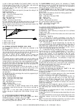
4.10.2 - ALARMS HYSTERESIS
The alarm function depend s on alarm hysteresis (par. "HAL1"),
which works in asymmetric way.
In the event of low alarm, the alarm will be activated when the
process value goes below the alarm threshold value and will be
deactivated when it goes above the alarm threshold + "HAL1" ; in
case of high alarm, the alarm will be activated when the process
value goes above the alarm threshold value and will be deactivated
when it goes below the alarm threshold - "HAL1".
For the band alarms, the example of the low alarm is applicable to
the low threshold ("AL1L") while the example of the high alarm is
applicable to the high threshold ("AL1H").


