


ELCO S.r.l. - ELK 38 - OPERATING INSTRUCTIONS - Vr. 02 - ISTR 06261 - PAG. 2
E : Thermocouples temperature probes (J,K,S and ELCO IRS
Infrared sensors), mV signals (0..50/60 mV, 12..60 mV),
Thermistors PTC and NTC.
I : normalized analogue signals 0/4..20 mA
V : normalized analogue signals 0..1 V, 0/1..5 V, 0/2..10 V
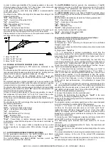
Other important available functions are: Loop-Break Alarm function,
reaching of the Set Point at controlled speed, ramp and dwell
function, Soft-Start function, protection compressor function for
neutral zone control, parameters protection on different levels.
1.2
-
FRONT PANEL DESCRIPTION
1 - Key P : This is used to access the programming parameters and
to confirm selection.
2 - Key DOWN : This is used to decrease the values to be set and
to select the parameters. If the key is held down, the user returns to
the previous programming level until he exits the programming
mode. Outside the programming mode it permits visualisation of the
current measured by the TAHB input.
3 - Key UP : This is used to increase the values to be set and to
select the parameters. If the key is held down, the user returns to
the previous programming level until he exits the programming
mode. Outside the programming mode it permits visualisation of the
output control power.
4 - Key U : This is a key with a function programmable by par.
“USrb”. It can be set to : Activate Auto-tuning and Self-tuning
functions, swap the instrument to manual control, silence the alarm,
change the active Set Point, deactivate control.
5 - Led OUT1 : indicates the state of output OUT1
6 - Led OUT2 : indicates the state of output OUT2
7 - Led SET : when flashing, it indicates access to the programming
mode.
8 - Led AT/ST : indicates that the Self-tuning function is activated
(light on) or that Auto-tuning (flashing ) is in progress.
9 - Led – Shift index: indicates that the process value is lower than
the one programmed on par. “AdE”.
10 - Led = Shift index: indicates that the process value is within the
range [SP+AdE ... SP-AdE]
11 - Led + Shift index: indicates that the process value is higher
than the one set on par. “AdE”.
2 - PROGRAMMING
2 .1 - FAST PROGRAMMING OF THE SET POINT
This procedure permits rapid programming of the active Set Point
and possibly the alarm thresholds (see par 2.3)
Push key “P”, then release it and the display will visualise “SP n”
(where n is the number of the Set Point active at that moment)
alternatively to the programmed value.
To modify the value, press “UP” key to increase it or the “DOWN”
key to decrease it.
These keys change the value one digit at a time but if they are
pressed for more than one second, the value increases or
decreases rapidly and, after two seconds in the same condition, the
changing speed increases in order to allow the desired value to be
reached rapidly.
Once the desired value has been reached, by pushing key P it is
possible to exit by the fast programming mode or it is possible to
visualise the alarm thresholds (see par. 2.3).
To exit the fast Set programming it is necessary to push key P, after
the visualisation of the last Set Point, or alternatively, if no key is
pressed for approx. 15 seconds, the display will return to normal
functioning automatically.
2.2 - SELECTION OF THE CONTROL STATE AND PARAMETER
PROGRAMMING
By pushing key "P" and holding it down for approx. 2 sec. it is
possible to enter into the main selection menu.
Using the "UP" or DOWN” keys, it is then possible to roll over the
selections:
"OPEr"
to enter into the operating parameters menu
"ConF"
to enter into the configuration parameters menu
"OFF"
to swap the regulator into the OFF state
"rEG"
to swap the regulator into the automatic control state
"tunE"
to activate the Auto-tuning or Self-tuning function
"OPLO"
to swap the regulator to the manual control state and
therefore to program the % control value using the
“UP” and “DOWN” keys
Once the desired item has been selected, push key “P” to confirm.
Selecting "OPEr" and "ConF" gives the possibility of accessing other
menus containing additional parameters and more precisely :
"OPEr" - Operating parameters Menu: this normally contains the
Set Point parameters but it can contain all the desired parameters
(see par. 2.3).
"ConF" - Configuration parameters Menu: this contains all the
operating parameters and the functioning configuration parameters
(alarm configuration, control, input, etc.)
To enter the menu “OPEr”, select the option “OPEr” and press the
key “P”.
The display will now show the code identifying the first group of
parameters (“
]
SP “) and by pressing the “UP” and “DOWN” keys it
will be possible to select the group of parameters to be modified.
Once the desired group of parameters has been selected, the code
identifying the first parameter of the selected group will be visualised
by pushing the “P” key.
Again using the “UP” and “DOWN” keys, it is possible to select the
desired parameter and, if the key “P” is pressed, the display will
alternatively show the parameter’s code and its programming value,
which can be modified by using the “UP” or “DOWN” keys.
Once the desired value has been programmed, push key “P” once
more: the new value will be memorised and the display will show
only the code of the selected parameter.
By using the “UP” or “DOWN” keys, it is then possible to select a
new parameter (if present) and modify it as described above.
To select another group of parameters, keep the “UP” or “DOWN”
key pressed for approx. 2 sec., afterwards the display will return to
visualise the code of the group of parameters.
ELK


