


ELCO S.r.l. - ELK 38 - OPERATING INSTRUCTIONS - Vr. 02 - ISTR 06261 - PAG. 13
Usrb – KEY U FUNCTION : Decides which function is associated to
key U. The possible selections are :
= noF : no function
= tunE : Pushing the key for 1 sec. at least, it is possible to
activate/deactivate the Auto-tuning or the Self-tuning
= OPLO : Pushing the key for 1 sec. at least, it is possible to swap
from the automatic control (rEG) to the manual one (OPLO) and vice
versa.
= Aac : Pushing the key for 1 sec. at least, it is possible to
acknowledge the alarm.
= ASi : Pushing the key for 1 sec. at least, it is possible to
acknowledge an active alarm
= CHSP : Pushing the key for 1 sec. at least, it is possible to select
one of the 4 pre-programmed Set Points on rotation.
= OFF : Pushing the key for 1 sec. at least, it is possible to swap
from the automatic control (rEG) to the OFF control (OFF) and vice
versa.
diSP - VARIABLE VISUALISED ON THE DISPLAY: Parameter
through which it is possible to decide what is visualised on the
display : the process variable (= dEF), the control power (= Pou), the
active Set Point (= SP.F), the Set Point active when there are ramps
(= SP.o) or the alarm threshold AL1 (= AL1).
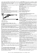
AdE - SHIFT VALUE FOR THE SHIFT INDEX FUNCTIONING: This
allows one to decide the functioning mode of the 3 led shift indexes.
The lighting of the green led “=” indicates that the process value is
within the range [SP+AdE ... SP-AdE], the lighting of the red led “-”
indicates that the process value is lower than the value [SP-AdE]
and the lighting of the red led “+”indicates that the process value is
higher than the value [SP+AdE].
Edit - FAST PROGRAMMING OF ACTIVE SET POINT AND
ALARMS: This decides which are the Sets that can be programmed
by the fast procedure. The parameter can be programmed as :
=SE: The active Set Point can be modified while the alarm
thresholds cannot be modified
=AE :The active Set Point cannot be modified while the alarm
thresholds can be modified
=SAE: If the active Set Point or the alarm thresholds can be
modified
=SAnE: If the active Set Point or the alarm thresholds cannot be
modified
6 - PROBLEMS, MAINTENANCE AND GUARANTEE
6.1 - ERROR SIGNALLING
Error
Reason
Action
- - - -
Probe interrupted
Verify
the
correct
connection
between
probe and instrument and
then verify the correct
functioning of the probe
uuuu
The measured variable
is under the probe’s
limits (under-range)
oooo
The measured variable
is over the probe’s
limits (over-range)
ErAt
Auto-tuning
not
possible because the
process value is higher
(with
“Func”
=HEAt)
than [SP- |SP/2|] or
lower
(with
“Func”
=CooL)
than
[SP+
|SP/2|].
Swap the instrument to
OFF control (OFF) and
then to automatic control
(rEG) in order to make the
error message disappear.
Once the error has been
found, try to repeat the
auto-tuning.
noAt
Auto-tuning not finished
within 12 hours
Check the functioning of
probe and actuator and
try to repeat the auto-
tuning.
LbA
Loop control interrupted
(Loop break alarm)
Check the working of
probe and actuator and
swap the instrument to
(rEG) control
ErEP
Possible anomaly of the
EEPROM memory
Push key “P”
In error conditions, the instrument provides an output power as
programmed on par “OPE” and activates the desired alarms, if the
relative parameters “ALni” have been programmed = yES.
6.2 - CLEANING
We recommend cleaning of the instrument with a slightly wet cloth
using water and not abrasive cleaners or solvents which may
damage the instrument.
6.3 - GUARANTEE AND REPAIRS
The instrument is under warranty against manufacturing flaws or
faulty material, that are found within 12 months from delivery date.
The guarantee is limited to repairs or to the replacement of the
instrument.
The eventual opening of the housing, the violation of the instrument
or the improper use and installation of the product will bring about
the immediate withdrawal of the warranty’s effects.
In the event of a faulty instrument, either within the period of
warranty, or further to its expiry, please contact our sales
department to obtain authorisation for sending the instrument to our
company.
The faulty product must be shipped to ELCO with a detailed
description of the faults found, without any fees or charge for ELCO,
except in the event of alternative agreements.
7 - TECHNICAL DATA
7.1 – ELECTRICAL DATA
Power supply: 12 VAC/VDC, 24, 115, 230 VAC, 24 VAC/VDC, 100..
240 VAC +/- 10%
Frequency AC: 50/60 Hz
Power consumption: 4 VA approx.
Input/s: 1 input for temperature probes: tc J,K,S ; infrared sensors
ELCO IRS J e K; RTD Pt 100 IEC; PTC KTY 81-121 (990
Ω
@ 25
°C); NTC 103AT-2 (10K
Ω
@ 25 °C) or mV signals 0...50 mV, 0...60
mV, 12 ...60 mV or normalized signals 0/4...20 mA, 0..1 V, 0/1...5 V
, 0/2...10 V.
Normalized signals input impedance: 0/4..20 mA: 51
Ω
; mV and V:
1 M
Ω
Output/s: Up to 2 outputs. Relay SPDT (8 A-AC1, 3 A-AC3 / 250
VAC) ; or in tension to drive SSR (8mA/ 8VDC).
Auxiliary supply output: 12 VDC / 20 mA Max.
Electrical life for relay outputs: 100000 operat.
Installation category: II
Measurement category: I
Protection class against electric shock: Class II for Front panel
Insulation:
Reinforced insulation between the low voltage part (power supply
115 or 230 V and relay outputs) and front panel; Reinforced
insulation between the low voltage section (Supply 115 or 230 V and
relay outputs) and the extra low voltage section (input, SSR
outputs); Reinforced between power supply and relay; No insulation
between supply 12 V and input. No insulation between input and
SSR outputs.
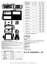
7.2 – MECHANICAL DATA
Housing: Self-extinguishing plastic, UL 94 V0
Dimensions: 33 x 75 mm, depth 64 mm
Weight: 180 g approx.
Mounting: Flush in panel in 29 x 71 mm hole
Connections: 2,5 mm
2
screw terminals block
Degree of front panel protection : IP 65 mounted in panel with
gasket
Pollution situation: 2
Operating temperature: 0 ... 50 °C
Operating humidity: 30 ... 95 RH% without condensation
Storage temperature: -10 ... +60 °C
7.3 – MECHANICAL DIMENSIONS, PANEL CUT-OUT AND
MOUNTING [mm]


