


26
Fig. 7.6
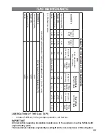
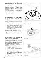
REPLACEMENT OF THE INJECTORS
If the injectors are not supplied they can
be obtained from the “Service Centre”.
Select the injectors to be replaced accor-
ding to the “Table for the choice of the
injectors”.
The nozzle diameters, expressed in hun-
dredths of a millimetre, are marked on the
body of each injector.
REPLACEMENT OF THE INJEC-
TORS OF THE COOKTOP BUR-
NERS
To replace the injectors proceed as follows:
•
Remove pan supports and burners
from the cooktop.
•
Using a wrench, substitute the nozzle
injectors “
J
” (figs. 7.5a - 7.5b) with tho
-
se most suitable for the kind of gas for
which it is to be used.
The burners are conceived in such a
way so as not to require the regulation
of the primary air.
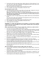
ADJUSTING OF THE MINIMUM OF
THE COOKTOP BURNERS
In the minimum position the flame must
have a length of about 4 mm and must re-
main lit even with a quick turn from the ma-
ximum position to that of minimum.
The flame adjustment is done in the fol
-
lowing way:
•
Turn on the burner.
•
Turn the tap to the MINIMUM position.
•
Take off the knob.
•
With a small flat screwdriver turn the
screw inside the tap rod to the correct
regulation (fig. 7.6).
Normally for G30/G31 (LPG), tighten up
the regulation screw.
J
Fig. 7.5a
J
Fig. 7.5b
Semi-rapid and
rapid burners
Triple-ring burner
Summary of Contents for EGC 833 series
Page 14: ...14 A B S Fig 5 4 Fig 5 5 Fig 5 6 S F C Fig 5 3 Fig 5 2...
Page 30: ...30...
Page 31: ...31...