


© ELAN Home Systems 2008 • All rights reserved. Page 13
E L A N H O M E S Y S T E M S
XP8.4
Wireless Color Touch Panel
Applications
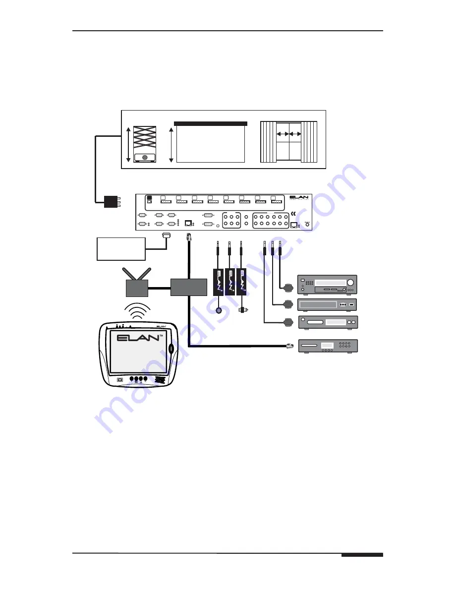
Stand-Alone/Home Theater
The XP8.4 Wireless Color Touch Panel can be used for any Stand-Alone
(non-ELAN) system application or as a Home Theater controller.
Figure 2-2
shows a basic application
AUDIO SENSOR
CONT
ACT SENSOR
LED/LIGHT SENSOR
Router
Relay
Screen
Lift
Drapes
IR Emitter
IR Emitter
IR Emitter
SS1
Wireless
Access
Point
VIA!dj
ELAN SENSE
Sensors
®
Relay Controlled Devices (x8)
Home Theater
Components
IR Outputs (x12)
Sense Inputs (x6)
Local One-Way
RS-232 Controlled
Devices (x4)
ETHERNET
RS-232
HOST RS-232
ELAN RS-232
HOST
ELAN
COM 1
COM 3
COM 2
COM 4
COM1
COM2
COM3
COM4
ETHERNET
LINK
RX/TX
IR-LINK
SENSE INPUTS
1
2
3
4
5
6
ALL IR OUTPUT
EXT IR INPUT
IR OUTPUTS
1
7
2
8
3
9
4
10
5
11
6
12
VIA-NET
IR
PWR
VIA!2SS1
POWER
12VDC
0.5 AMPS
-
+
LEXINGTON, KY • MADE IN CHINA
MODEL:
VIA2SS1
WARNING:
DO NOT REMOVE COVER.
NO USER SERVICEABLE PARTS INSIDE.
REFER SERVICE TO ELAN-APPROVED
SERVICE TECHNICIAN.
PWR
GND
NC
COM
NO
PWR
GND
NC
COM
NO
PWR
GND
NC
COM
NO
PWR
GND
NC
COM
NO
PWR
GND
NC
COM
NO
PWR
GND
NC
COM
NO
PWR
GND
NC
COM
NO
PWR
GND
NC
COM
NO
PWR
GND
DC RELAY PWR
RELAY 1
RELAY 2
RELAY 3
RELAY 4
RELAY 5
RELAY 6
RELAY 7
RELAY 8
Wireless
Touch Panel
XP84
Figure 2-2: Stand-Alone/Home Theater Application


