background image

   © ELAN Home Systems  2008 • All rights reserved.                      Page 27

E L A N   H O M E   S Y S T E M S                

XP8.4

 Wireless Color Touch Panel

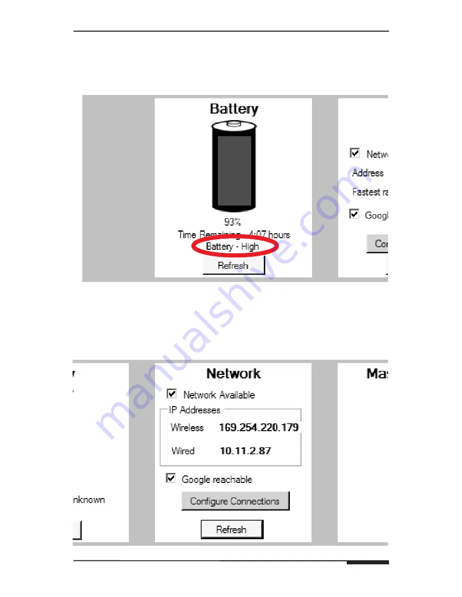
Battery Level Indicator

The first field on the top left is the 

Battery Level Indicator. 

Tapping the 

Refresh

 button will update the current 

Status

Charge Percentage

Time 

Remaining,

 and 

Status

 are available when viewing this field. When placed 

on the 

Docking Station

 the display will switch to 

AC Power

 from 

Battery.

Figure 4-8: Battery Level Indicator

Network

Next is the 

Network Connectivity

 field. This field is used to edit and cre-

ate Internet connections. This field contains two selections: 

Configure 

Connections

 and 

Refresh

. See 

Connection Setup 

on

 page 40 

for details. 

See 

Appendix C: Wireless Networking 

for more information on wireless 

network setup and equipment. 

Figure 4-9: Network Settings

Summary of Contents for XP84

Page 1: ......

Page 2: ......

Page 3: ...nformation The safety and operating information should be retained for future reference Heed Warnings All warnings on the appliance and in the operating instructions should be heeded Wall Mounting Mou...

Page 4: ...oltage surges and built up static charg es Section 810 of the U S National Electrical Code and Section 54 of the Canadian Electrical Code provide information with respect to proper grounding of the ma...

Page 5: ...lug this apparatus during lightning storms or when unused for long periods of time Attachments and Accessories Use only attachments accessories specified by the manufacturer Cart Stand Tripod Bracket...

Page 6: ...vice other than as instructed in this guide Do not drop knock or shake the device Rough handling can break internal circuit boards and fine mechanics Do not use harsh chemicals cleaning solvents or st...

Page 7: ...atures 6 Quick Reference 7 Callouts 8 2 System Design Applications 11 Pre Wire 12 Applications 13 3 Connections 18 System Interface Connections 19 4 Operation Setup 22 Device Control 23 System Setup 2...

Page 8: ...ay screen The color LCD display is an active matrix TFT Liquid Crystal Display Depressing the polyester film with the included stylus allows the film to touch the glass panel underneath generating a l...

Page 9: ...ved Page 7 ELAN HOME SY ST E M S XP8 4 Wireless Color Touch Panel XP8 4 Quick Reference Card The XP8 4 is packaged with a Quick reference Card to allow users to quickly access all of the features of t...

Page 10: ...tivates the touch screen keyboard 3 Settings Activates the Settings screen 4 Button 2 Programmable hard button for macro sequences or for activating applications 5 Speakers Provides sound for web brow...

Page 11: ...Orange Low Battery Side Panel Right The right side of the XP8 4 features ports for connection of Power supply Microphone and Headphones There is also storage for the Stylus and a MUTE control button 1...

Page 12: ...ide Panel Left The left side of the XP8 4 features a Power button The USB port is not appli cable 1 2 Bottom Top Figure 1 6 Side Panel Left Item Port Item Description 1 Power Button Push release enter...

Page 13: ...t locations etc Ensure that all locations are decided upon before pre wiring commences so that all necessary wiring and installation hardware is in place This unit will be interfacing with other compo...

Page 14: ...e each installtion different Test the range before finalizing the installation locations of WAPs Note ELAN strongly recommends a WAP in each zone that contains a wireless touch panel Router A Router i...

Page 15: ...Local One Way RS 232 Controlled Devices x4 ETHERNET RS 232 HOST RS 232 ELAN RS 232 HOST ELAN COM 1 COM 3 COM 2 COM 4 COM1 COM2 COM3 COM4 ETHERNET LINK RX TX IR LINK SENSE INPUTS 1 2 3 4 5 6 ALL IR OU...

Page 16: ...PWR GND NC COM NO PWR GND DC RELAY PWR RELAY 1 RELAY 2 RELAY 3 RELAY 4 RELAY 5 RELAY 6 RELAY 7 RELAY 8 S 12 VIA Net Ol Relay Gate Relay Controlled Devices x8 Garage Door AUDIO SENSOR CONTACT SENSOR L...

Page 17: ...ND NC COM NO PWR GND NC COM NO PWR GND NC COM NO PWR GND DC RELAY PWR RELAY 1 RELAY 2 RELAY 3 RELAY 4 RELAY 5 RELAY 6 RELAY 7 RELAY 8 VIA NET Ol Relay Gate Relay Controlled Devices x8 AUDIO SENSOR CON...

Page 18: ...t Drapes IR Emitter IR Emitter IR Emitter ZONE SS1 Wireless Access Point VIA dvdj ELAN SENSE Sensors Relay Controlled Devices x8 Home Theater Components IR Outputs x12 Sense Inputs x6 Local One Way RS...

Page 19: ...ontrolled Devices x8 Home Theater Components IR Outputs x12 Sense Inputs x6 Local One Way RS 232 Controlled Devices x4 ETHERNET RS 232 HOST RS 232 ELAN RS 232 HOST ELAN COM 1 COM 3 COM 2 COM 4 COM1 CO...

Page 20: ...The transformer can be connected directly to the panel instead of the cradle if so desired The char ger port is located on the right side of the panel as shown in Figure 1 5 Note The USB ports on the...

Page 21: ...XT IR INPUT IR OUTPUTS 1 2 3 4 5 6 7 8 9 10 11 12 VIA NET PWR IR VIA2SS POWER 16VDC LEXINGTON KY MADE IN CHINA MODEL VIA2SS1 WARNING DO NOT REMOVE COVER NO USER SERVICEABLE PARTS INSIDE REFER SERVICE...

Page 22: ...m Controller based system ZONE applications can provide IR routing in order to control local IR sources IR zone control IR control of system wide sources one way and two way control if part of a Syste...

Page 23: ...485 N C 12V G N C INT EXT EXT INT N C IR 485 485 N C 12V G N C Z2C 12V OL ZPAD N C IR 485 485 G V G V Z2B 16V 12V VIA OL N C IR 485 485 G 16V G 16V Z2A 16V VIA OL S6 S12 ZNET S8 6 S12 8 VNET INT EXT I...

Page 24: ...s to oper ate the touch screen The stylus for the XP8 4 touch screen is located in the upper right corner of the panel and slides out from the chassis easily Stylus Figure 4 1 XP8 4 Side View Control...

Page 25: ...ontrols and other interactive interface components tap them once with the stylus A single tap may open a list activate a button in a dialog or a link on a web page select a check box and activate a te...

Page 26: ...Key Adds a tabulator space or moves the cursor to the next available text input field 2 Caps Key Locks the uppercase characters of the keyboard 3 Shift Key When you tap this key the lowercase charact...

Page 27: ...order for the XP8 4 to function A Wireless Access Point WAP and Router or Router WAP combination must be in place and in range of the XP8 4 See Appendix C Wireless Networking for greater details of wi...

Page 28: ...ELAN Devices button brings up the device Name Type and IP Address Figure 4 6 Control Panel ELAN Devices Settings The Settings button brings up the Settings page The following choices are available Ba...

Page 29: ...e available when viewing this field When placed on the Docking Station the display will switch to AC Power from Battery Figure 4 8 Battery Level Indicator Network Next is the Network Connectivity fiel...

Page 30: ...ator Use the stylus to adjust the Volume slider from Min to Max to set the Master Volume Check the Mute box to disable the XP8 4 s audio Figure 4 10 Volume Level Indicator Date and Time Select Date an...

Page 31: ...ELAN Home Systems 2008 All rights reserved Page 29 ELAN HOME SY ST E M S XP8 4 Wireless Color Touch Panel Figure 4 12 Date and Time Date Figure 4 13 Daylight Savings Time Figure 4 14 Internet Time...

Page 32: ...een Calibration from the Settings page The calibration sequence consists of touching and holding the screen in five different places Use the stylus and tap and hold where indicated on the touch screen...

Page 33: ...Battery allows for quicker power down time for the monitor and hard disk when the XP84 is running on batteries Figure 4 17 Power Schemes Settings The Low battery and Critical battery alarms are adjus...

Page 34: ...nd Total time remaining are given Tapping on each battery icon displays detailed information for that battery such as name I D Chemical composition and manufacturer Figure 4 19 Power Meter Settings Th...

Page 35: ...huts down after a period of non use When the XP84 comes out of hibernation it returns to its previous state Free disk space is required to allow the XP84 to Hibernate Figure 4 21 Hibernate Settings Sc...

Page 36: ...sword The Download screen will then be displayed as shown in Figure 4 23 Figure 4 23 Control Panel Installer Note This section assumes that a wireless home network is installed and working correctly I...

Page 37: ...lor Touch Panel Figure 4 24 Download Enabled To download VIA TOOLS programming to the XP8 4 Select the XP8 4 s Enable button under Download Timeout Press the Download Enable Button on the SS1 IR LINK...

Page 38: ...the Transfer Page and select the Transfer to SS and or VIA 2 button Figure 4 26 VIA TOOLS Transfer Page The Transfer Page will pop up Select Scan Figure 4 27 VIA TOOLS Transfer Page Scan The scanning...

Page 39: ...Transfer to initiate download to both the SS1 and XP8 4 Once the progress bars have indicated that the download is complete press Done Customer Data The customer name zipcode dealer name and dealer p...

Page 40: ...he programming on the XP8 4 must be reset to reflect this change TGM 100 To set a static IP address for a TGM 100 Digital Music Server Press Set TGM 100 Address A window labeled TGM 100 will appear Th...

Page 41: ...8 All rights reserved Page 39 ELAN HOME SY ST E M S XP8 4 Wireless Color Touch Panel Note ELAN strongly recommends Updating the XP8 4 after getting it on the home network Figure 4 31 Update Figure 4 3...

Page 42: ...Edit connections Select Configure Connections Select Wireless Network Connection then select View Available Wireless Networks from the Network Tasks menu Figure 4 33 Network Connectivity Configure Co...

Page 43: ...Network Connection Note When the XP8 4 is connected to a DHCP Router via its Docking Station a Wired Network Connection is established and the IP Address is displayed in the Network Window as shown in...

Page 44: ...ights reserved Network Key Enter the network key also called a WEP key or a WPA key A network key helps prevent unknown intruders from connecting to the network Then confirm the network key Select Con...

Page 45: ...on hold the stylus on the selection and then select Properties Under the General tab go to This connection uses the following items and scroll down to Internet Protocol TCP IP and double tap Select Us...

Page 46: ...int Select the Wireless Network Connection select View Wireless Network Connection from the Network Tasks menu Select Change the order of preferred networks from the Related Tasks window The Wireless...

Page 47: ...The Homepage will open and be displayed Figure 4 42 Web Browser Button Note See VIA Tools Help file for XP8 4 Browser programming details Figure 4 43 Homepage Open and Browse Web Pages To open a web p...

Page 48: ...e in Web Address To reload a page Tap the stylus on the refresh icon green arrows or tap F5 on the On Screen key board To stop loading the the page tap the X icon To browse and scroll a web page With...

Page 49: ...elect the Screen Minimize icon in the top right corner For more information see the XP8 4 help file Favorites To add a Favorite to the current web page Select Favorites from the browser bar menu as sh...

Page 50: ...th a provider such as Yahoo MSN Google etc Cache A cache is a memory location that is used to store data temporarily If you have accessed confidential information requiring passwords empty the cache a...

Page 51: ...nal battery pack that clips hot pluggable onto the back of the XP84 The period between battery recharges can be significantly lengthened by putting the XP84 into Standby mode with the Power Button whe...

Page 52: ...S Page 50 ELAN Home Systems 2008 All rights reserved To remove the external battery pack Remove the battery from the unit by pressing in on the side tabs and lift out Replace rubber cover if not usin...

Page 53: ...wnload steps in this manual and in VIA TOOLS Help file XP8 4 won t control devic es zones etc 1 Router locked up Reset Reboot Router Reset Reboot SS1 2 XP8 4 and or Router security settings incorrect...

Page 54: ...0 Software Operating System Windows XP Embedded Memory storage RAM 512MB Flash 1GB Network Interface Integrated 802 11 a b g Input Ports 12V DC in Jack Microphone In Headset jack Enclosure Magnesium A...

Page 55: ...10 5 11 6 12 VIA NET IR PWR SS1 POWER 12VDC 0 5 AMPS LEXINGTON KY MADE IN CHINA MODEL SS1 SYSTEM STATION WARNING DO NOT REMOVE COVER NO USER SERVICEABLE PARTS INSIDE REFER SERVICE TO ELAN APPROVED SER...

Page 56: ...please con sult the SS1 Installation Manual SENSE INPUTS ELAN RS 232 ALL IR OUTPUT EXT IR INPUT IR OUTPUTS 1 7 2 8 3 9 4 10 5 11 6 12 IR PWR VIA NET SS1 POWER 12VDC 0 5 AMPS HOST ELAN COM3 COM4 ETHER...

Page 57: ...interference from microwave ovens cordless phones and other appliances using the same 2 4 GHz band Note ELAN strongly recommends an AP Wireless Router in each zone that contains a wireless touch pane...

Page 58: ...XP8 4 Wireless Color Touch Panel EL AN HO M E S YST E M S Page 56 ELAN Home Systems 2008 All rights reserved Notes...

Page 59: ......

Page 60: ...quipment sold by but not manufactured by ELAN the warranty obligations of ELAN shall in all respects conform to the warranty actually extended to ELAN by its supplier The foregoing warranties do not c...

Page 61: ...962 REV A INK BLACK MATERIAL 60 LB WHITE COATED PAPER SCALE 1 1 SIZE 11 000 X 8 500 TOL 040 FOLDING ALBUM FOLD CENTER STAPLE FOLD TO 5 500 X 8 500 PAGES 60 NOTE ARTWORK CREATED BY ELAN HOME SYSTEMS TH...

Page 62: ......

Reviews: