background image

English 

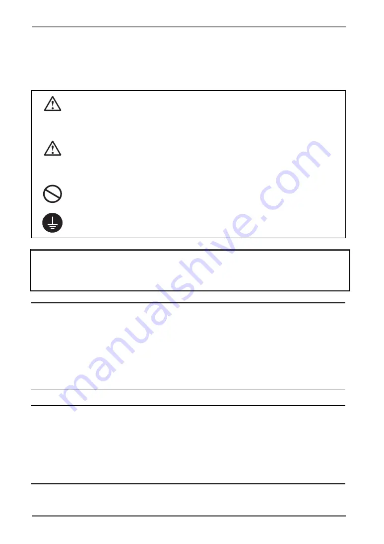
SAFETY SYMBOLS 

This manual uses the safety symbols below.  They denote critical information.  Please read them 
carefully. 


WARNING 

Failure to abide by the information in a WARNING may result in serious injury and 
can be life threatening. 


CAUTION 

Failure to abide by the information in a CAUTION may result in moderate injury 
and/or property or product damage. 


Indicates a prohibited action. 


Indicates to ground for safety. 


• 

Power supplied equipment can emit electromagnetic waves, that could influence, limit or 
result in malfunction of the monitor.  Install the equipment in a controlled environment, where 
such effects are avoided. 

• 

This is a monitor intended for use in a medical image system. 


Copyright© 2005 EIZO NANAO CORPORATION All rights reserved.  No part of this manual 
may be reproduced, stored in a retrieval system, or transmitted, in any form or by any means, 
electronic, mechanical, or otherwise, without the prior written permission of EIZO NANAO 
CORPORATION. 
EIZO NANAO CORPORATION is under no obligation to hold any submitted material or 
information confidential unless prior arrangements are made pursuant to EIZO NANAO 
CORPORATION's receipt of said information.  Although every effort has been made to ensure 
that this manual provides up-to-date information, please note that EIZO monitor specifications 
are subject to change without notice. 


Apple and Macintosh are registered trademarks of Apple Computer, Inc. 
VGA is a registered trademark of International Business Machines Corporation. 
DPMS is a trademark and VESA is a registered trademark of Video Electronics Standards 
Association. 
Windows is a registered trademark of Microsoft Corporation. 
PowerManager, RadiCS and RadiNET Pro are trademarks of EIZO NANAO CORPORATION. 
ScreenManager, RadiForce and EIZO are registered trademarks of EIZO NANAO 
CORPORATION in Japan and other countries. 

2


Summary of Contents for RadiForce G33

Page 1: ...User s Manual Monochrome LCD Monitor It shall be assured that the final system is in compliance to IEC60601 1 1 requirements...

Page 2: ...transmitted in any form or by any means electronic mechanical or otherwise without the prior written permission of EIZO NANAO CORPORATION EIZO NANAO CORPORATION is under no obligation to hold any sub...

Page 3: ...ble Connection 12 3 MENUS FUNCTIONS 15 3 1 ScreenManager 15 3 2 CAL Switch Function 17 3 3 Other Useful Functions 18 4 ADJUSTMENTS SETTINGS 21 4 1 Brightness Adjustment 21 4 2 Image Adjustments 21 4 3...

Page 4: ...ginally shipped If operated outside the region to which it was originally shipped the product may not perform as stated in the specifications To ensure personal safety and proper maintenance please re...

Page 5: ...ked by a qualified service engineer before using it again Place the unit at the strong and stable place A unit placed on an inadequate surface may fall and result in injury or equipment damage If the...

Page 6: ...English WARNING To disconnect the power cord grasp the plug firmly and pull Tugging on the cord may damage and result in fire or electric shock...

Page 7: ...power cord and cables when moving the unit Moving the unit with the cord attached is dangerous It may result in injury When handling the unit grip the bottom of the unit firmly with both hands ensuri...

Page 8: ...te or damage your LCD panel Leave the screen white to decrease the prints Do not scratch or press on the panel with any sharp objects such as a pencil or pen as this may result in damage to the panel...

Page 9: ...Disk Monitor stand adjustable for different heights Ultra slim bezel 12bit monochrome signal input support 2 1 This sensor is used when calibrating the monitor with the exclusive software RadiNET Pro...

Page 10: ...English 1 3 Controls Connectors Front...

Page 11: ...English Side Rear...

Page 12: ...de Resolution Frequency Dot Clock Portrait Landscape 720 400 VGA TEXT 70 Hz 640 480 VGA 60 Hz 1536 1024 3M Packed Pixel 60 Hz 1024 1536 3M Packed Pixel 60 Hz 165 MHz Max Supported 2 2 Cable Connection...

Page 13: ...he power connector on the rear of the monitor 4 Thread the power cord and signal cable through the cable holder on the rear of the monitor stand NOTE When threading the cables through the cable holder...

Page 14: ...on the PC s power If an image does not appear refer to 7 TROUBLESHOOTING see p 26 for additional advice When finished turn off the PC and the monitor NOTE Adjust the brightness of the screen depending...

Page 15: ...witch 2 Select the desired setting icon with the directing switches and touch the enter switch 3 Make any required adjustments with the directing switches Exiting the ScreenManager 1 To return to the...

Page 16: ...specified time see p 20 Menu Position Adjust the menu position Menu Settings Menu Off Timer Adjust how long to display the menu 1 Power Indicator Disable the green power indicator see p 19 Others Res...

Page 17: ...p 31 How to use the CAL Switch Function Entering the CAL Switch menu 1 Touch the mode switch Selecting the CAL Switch mode 1 Touch the mode switch while the CAL Switch menu is displayed Making bright...

Page 18: ...Option Monitor Orientation Display Example Landscape Select this option when using the Landscape orientation A A Landscape Portrait Portrait SW Select this option when using the Portrait orientation T...

Page 19: ...u 2 Select Disable Adjustment Lock Use this function to prevent any accidental changes to the monitor settings The following table shows which functions the adjustment lock affects Locked functions Di...

Page 20: ...Period 1 to 23 hours Off timer system PC Monitor Power Indicator On Period 1H 23H Operational Green Last 15 min in On period Advance Notice 1 Flashing green On period expired Power off Flashing orang...

Page 21: ...t Border in the ScreenManager Others menu 2 Make adjustments with the Left and Right directing switches The Left directing switch makes the border darker and the Right directing switch makes it bright...

Page 22: ...DMPM in the PowerManager menu Power saving system PC Monitor Power Indicator On Operation Green Power saving Off mode Power saving Orange Power Resumption Procedure Click the mouse or press a key on...

Page 23: ...is not on the peripherals connected to the downstream ports will not operate Even if the monitor is in a power saving mode the devices connected to the monitor s USB ports both the upstream and the d...

Page 24: ...ecting Examples ScreenManager Pro for Medical for Windows For further details about the ScreenManager Pro for Medical for Windows refer to the EIZO LCD Utility Disk Downstream ports Connect the cables...

Page 25: ...x 100 mm VESA compliant Supportable Weight Total weight of the monitor without stand and attaching equipment such as a cable T V GS approved arm or stand Please connect cables after attaching an arm s...

Page 26: ...wer switch see p 20 2 One of the error messages shown below remains on the screen for 40 second These messages appear when the video signal is not input correctly even if the monitor functions properl...

Page 27: ...s Make sure not to wear gloves Remove any gloves and try touching the switches again with dry hands 8 The control panel does not operate CAL Switch mode does not operate Make sure the control panel sw...

Page 28: ...solved by doing this contact an EIZO dealer For details refer to the manual of the PC Try executing the following method Restarting the PC Connecting the PC and peripherals directly If the problem is...

Page 29: ...o turn off the monitor before cleaning it Cabinet To remove stains wipe the cabinet with a soft lightly moistened cloth using a mild detergent Do not spray wax or cleaner directly into the cabinet For...

Page 30: ...W for single signal input without USB Main power off 0 W Input Connector DVI D x 1 Input Signal TMDS Single Link Plug Play VESA DDC 2B EDID structure 1 3 With stand 368 0 mm W x 515 5 597 5 mm H x 20...

Page 31: ...Menu Settings Menu Off Timer 45 seconds Language English Optional Arm Stand EIZO LA 131 D EIZO LA 030 W EIZO LA 011 W LCD Monitor Flexible Arm Wall Mount Arm for LCD Monitor 8bit 10bit and 12bit monoc...

Page 32: ...7 18 22 23 24 Pin No Signal Pin No Signal Pin No Signal 1 TMDS Data2 9 TMDS Data1 17 TMDS Data0 2 TMDS Data2 10 TMDS Data1 18 TMDS Data0 3 TMDS Data2 4 Shield 11 TMDS Data1 3 Shield 19 TMDS Data0 5 Sh...

Page 33: ...or for digital signal input only and the DVI I connector for both digital and analog signal inputs DVI DMPM DVI Digital Monitor Power Management The Power management system for the digital interface T...

Page 34: ...rence to radio communications However there is no guarantee that interference will not occur in a particular installation If this equipment does cause harmful interference to radio or television recep...

Page 35: ...ecycling information is placed in the SWICO s website http www swico ch Recycling Information f r Kunden in der Schweiz Alle Informationen zum Thema Recycling finden Sie auf der Homepage des Brancheve...

Page 36: ......

Reviews: