background image

7

En

gli

sh


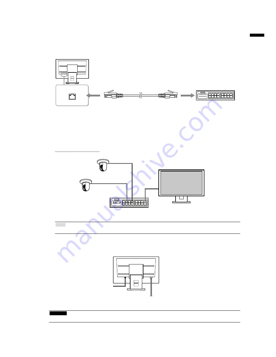
Connect the network camera(s)

Connect the network camera and the monitor according to the following procedure.

1. 

Connect the network camera to the monitor via the network hub.

1. 

Connect the network cable (straight cable, Cat 5e or higher) to the monitor and the LAN port of the 

network hub.

LAN

Network hub

*1

Network cable

(To 1000Base-T port)

*1 

Use a hub compatible with 1000Base-T. For some network cameras, the hub must be compatible with 

the PoE function. Check the network camera’s manual for information on the appropriate hub to use. 

2.  Connect the network camera to the network hub.

For connecting the network camera and the network hub, refer to the network camera’s manual.

Connection examples

Network camera

Network camera

Network hub

Note

• 

A maximum of 16 network cameras can be connected.

2. 

Plug the power cord into a power outlet and the power connector on the 

monitor.

To power outlet

Attention

•  Do not bundle cables when wiring.

Summary of Contents for DuraVision FDF2304W-P

Page 1: ...am durch um sich mit dem sicheren und effizienten Gebrauch vertraut zu machen Bewahren Sie dieses Handbuch zum sp teren Nachschlagen auf Die neueste Version des Handbuchs k nnen Sie auf unserer Websit...

Page 2: ...unit About this manual Setup Manual this manual Describes precautions and setup processes from network camera connection to camera image display Instruction Manual 1 Describes operation of network ca...

Page 3: ...lified service personnel Do not attempt to service this product yourself as opening or removing covers may result in fire electric shock or equipment damage Keep small objects or liquids away from the...

Page 4: ...t doing so may result in fire or electric shock Power supply 100 120 200 240 Vac 50 60Hz To disconnect the power cord grasp the plug firmly and pull Tugging on the cord may damage and result in fire o...

Page 5: ...es when moving the unit Moving the unit with the cord attached is dangerous It may result in injury When carrying the unit grasp and hold it firmly by the bottom as shown in the illustration on the ri...

Page 6: ...Package Contents 6 Setup 6 Setup Flow 6 Connect the network camera s 7 Prepare the remote control 8 Perform Easy Setup 9 Reference 17 How to Attach the Optional Arm 17 Connecting HDMI Devices 18 Speci...

Page 7: ...ocess refer to the corresponding pages Connect the network camera s page 7 Prepare the remote control page 8 Perform Easy Setup page 9 Set the following items using the setup wizard Date and time on t...

Page 8: ...e with 1000Base T For some network cameras the hub must be compatible with the PoE function Check the network camera s manual for information on the appropriate hub to use 2 Connect the network camera...

Page 9: ...l within the range illustrated in the diagram below 5m 5m 20 20 7m 5m 30 30 7m 5m When installing multiple monitors leave sufficient space between each monitor so that only the intended monitor will b...

Page 10: ...on the monitor The live image screen is displayed Menu Network camera image display area Message display area Note The monitor can also be turned on by pressing on the front of the monitor Attention...

Page 11: ...he list box is highlighted in green 2 Select the setting with or 3 Press When canceling a setting change in process press To return to the previous menu level Press 4 Check that Login is selected and...

Page 12: ...ter characters click Keyboard Then click the keys on the displayed keyboard to enter characters Entering network addresses Network address text fields are separated by a period mark When a three digit...

Page 13: ...press Select a setting with or and press 3 After completing the setting select Apply and press The setting complete screen is displayed Press to select OK 4 Press 5 Select Clock Setting and press 6 Se...

Page 14: ...list box of an item and press Input the respective values For details on the data entry method refer to To enter characters page 11 Attention If your network environment does not include a gateway yo...

Page 15: ...e default settings for Panasonic network cameras Change the settings if necessary 3 Select OK and press Searching is displayed Information on discovered network cameras are displayed 4 After the searc...

Page 16: ...isplay position you wish to set and press Select a network camera with or and press 3 After completing the setting press 4 Select Next and press Attention All cameras discovered at step 12 must be set...

Page 17: ...5 Close the setup screen 1 2 1 Select Return and press 2 Select Exit and press The screen returns to the live image screen Check that images from the network camera s are displayed on the monitor Exam...

Page 18: ...e stand and attachments such as cables When using an arm or stand attach it to meet the following tilt angles of the monitor Up 45 down 45 Do not turn the monitor in the vertical direction Connect the...

Page 19: ...z Max 720 400 VGA TEXT 70 Hz 720 480 4 3 CEA 861 60 Hz 720 480 16 9 CEA 861 60 Hz 720 576 4 3 CEA 861 50 Hz 720 576 16 9 CEA 861 50 Hz 800 600 VESA 60 Hz 1024 768 VESA 60 Hz 1280 720 CEA 861 60 Hz 128...

Page 20: ...e menu disappears automatically after approximately five seconds Specifying color space The color space of the input signal can be specified Change the settings when colors are not displayed accuratel...

Page 21: ...to 68 kHz 49 Hz to 61 Hz VGA TEXT 69 Hz to 71 Hz Applicable video signal formats 480 p 720 p 1080 p 60 Hz 576 p 720 p 1080 p 50 Hz USB Port Downstream port 2 Standard USB Specification Revision 2 0 Co...

Page 22: ...640 x 480 30 fps Attention The above values are provided for reference purposes Images are not displayed properly when display capability is exceeded because of network camera settings network install...

Page 23: ...22...

Page 24: ...Corporation All rights reserved http www eizoglobal com 153 Shimokashiwano Hakusan Ishikawa 924 8566 Japan Phone 81 76 277 6792 Fax 81 76 277 6793 Helmut Grashoff Strasse 18 41179 M nchengladbach Ger...

Reviews: