62
GPS 3 User Manual | 8103002-56
•
2018-07-17
3
Wait for GPS Solver to finish updating the sensor corrections.
Besides the changes occurring in the 3D model view, you will
see a “Please wait a moment” message at the top of the screen
and a “Detecting sensors” message next to the green progress
bar at the bottom of the screen.
4
Next, wait for GPS Solver to optimize its projections.
Again, besides seeing the sensors in the 3D model view changing
to blue and transparent blue labels appearing in the 2D model
view, you will see a “Please wait a moment” message at the top of
the screen and an “Optimizing projections” message next to the
green progress bar at the bottom of the screen.
5.2.3
Verify Sensor Placement
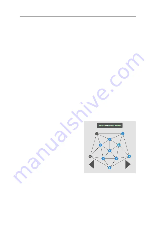
GPS Solver will prompt you when it is ready for this next stage.
You have several guides to help
you here:
•
One, the Status list will
keep track of the number
of cameras you have
completed.
•
Two, the dots in the
camera grid will change to
blue when they are
completed.
•
And, as always, the top message bar will prompt you for
sensors that need specific attention. See section 5.2.2.
Summary of Contents for Geodesic Photogrammetry System
Page 1: ......
Page 10: ...10 GPS 3 User Manual 8103002 56 2018 07 17...
Page 24: ...24 GPS 3 User Manual 8103002 56 2018 07 17...
Page 44: ...44 GPS 3 User Manual 8103002 56 2018 07 17...
Page 50: ...50 GPS 3 User Manual 8103002 56 2018 07 17 Figure 5 1 GPS Acquisition s Capture Images window...
Page 55: ...GPS 3 User Manual 8103002 56 2018 07 17 55...
Page 71: ...GPS 3 User Manual 8103002 56 2018 07 17 71...
Page 73: ...GPS 3 User Manual 8103002 56 2018 07 17 73 Figure A 2 64 channel GSN sensor layout...
Page 74: ...74 GPS 3 User Manual 8103002 56 2018 07 17 Figure A 3 128 channel GSN sensor layout...
Page 75: ...GPS 3 User Manual 8103002 56 2018 07 17 75 Figure A 4 256 channel GSN sensor layout...


