EFA M-VBE 6 User Manual Download Page 2

Mobile   animal   stunning   device   VBE-M   


2   


CAUTION!   


This   user   manual   is   an   integral   part   of   the   VBE-M   animal   stunning  


device.   It   is   absolutely   necessary   to  read  it  carefully  before  installing,  


commissioning   and   using   the   device.   


Please   contact   us   in   case   of   any   questions   or   concerns.   
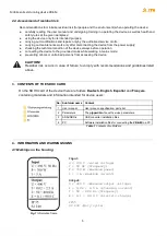


The    

stunning   system    

comes   equipped   with:   


1.

VBE-M    

animal   stunning   device   (called   the    

VBE-M   device 

)   


VBE-M    

stunning   unit   (called   the    

VBE-M 

)   


● power   system   


● trolley   with   tongs   cover   (called   the    

trolley 

)   


2. stunning   tongs   (called   the    

tongs 

)   


3. USB   converter   with   cable   (called   the  

  USB   converter 

)   


This   user   manual   applies   to   the   animal   stunning   device    

VBE-M 

.   


CAUTION!   


The   device   meets   the   requirements   of:   


Council   Regulation   (EC)   No   1099/2009   of   24   September   2009   on   the   protection   of  


animals   at   the   time   of   killing   ( 

Regulation   1099/2009 

); 


FSIS   Directive   6900.2   of   15   August   2011   -   “Humane   Handling   and   Slaughter   of  


Livestock”   ( 

FSIS   Directive 

).   


The    

SD   card    

contains   the    

user   manual    

of   the   device.   


TABLE   OF   

CONTENTS   


WORK   SAFETY   AND   OPERATING   RULES 

4  

OPIS   I   OCENA   RYZYKA   RESZTKOWEGO 

4  

2.1.   Description   of   residual   risk 

4  

2.2.   Assessment   of   residual   risk 

5  

CONTENTS   OF   THE   SDHC   CARD 

5  

INFORMATION   AND   WARNING   SIGNS 

5  

4.1   Markings   on   the   housing 

5  

4.2   Warning   and   information   pictograms 

6  

4.3   Signal   lights 

6  

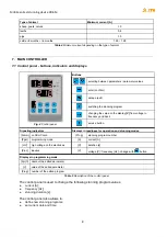
DESIGN,   TECHNICAL   DATA   AND   PARTS   LIST 

6  

5.1   Types   of   tongs 

7  

INTENDED   USE   AND   PRINCIPLE   OF   OPERATION 

7  

MAIN   CONTROLLER 

8  

7.1    Control   panel   -   buttons,   indicators   and   displays 

8  

Summary of Contents for M-VBE 6

Page 1: ...MOBILE ANIMAL STUNNING DEVICE VBE M MAULBRONN 1ST EDITION MAY 2021 Index number ________M0056 M Software version ____________E5 5 Serial number _____ ____ _____...

Page 2: ...BE M CAUTION The device meets the requirements of Council Regulation EC No 1099 2009 of 24 September 2009 on the protection of animals at the time of killing Regulation 1099 2009 FSIS Directive 6900 2...

Page 3: ...ng 18 10 2 Parameter reading 18 DOWNLOADING AND UPLOADING STUNNING PARAMETERS 19 11 1 Uploading parameters to the device from the SDHC card 19 11 2 Downloading parameters from the device to the SDHC c...

Page 4: ...to touch the electrodes CAUTION Wires and sockets of the device must not be exposed to water The inspection window of the device should always be tightly closed After finishing work it is absolutely...

Page 5: ...from accessing the device CAUTION Residual risk occurs in case of failure to comply with recommendations and guidelines listed above 3 CONTENTS OF THE SDHC CARD On the SDHC card of the device there ar...

Page 6: ...ronic equipment Do not connect the device to the mains if the connection or socket is damaged Do not wash with pressure washers Fig 2 Signal lights yellow light END OF STUNNING red light STUNNING gree...

Page 7: ...readiness for operation mode the device has been properly turned on and is ready for use stunning mode the device measures the animal s resistance starts the stunning process and maintains the set pa...

Page 8: ...define new stunning programs set current date and time Fig 4 Control panel Buttons selecting between parameters parameter values enter confirm escape exit switching the stunning program changing the...

Page 9: ...es not apply to VBE M YEAr setting the date year Mon setting the date month dAY setting the date day Hour setting the time hours Min setting the time minutes SEc setting the time seconds toFH s does n...

Page 10: ...f stunning phase 3 Setting dL3 to 0 cancels this phase The following parameters will then disappear from the menu Fr3b Fr3E SP3b SP3E tP3 Fr3b Hz initial frequency of stunning phase 3 The frequency ju...

Page 11: ...nning after the transition phase 12 head heart sinusoidal waveform suspension of stunning after the transition phase 13 head heart rectangular waveform suspension of stunning after the transition phas...

Page 12: ...over the device suspends the stunning the measuring voltage appears on the electrodes after removing the electrodes from the animal s head the device goes into the standby mode when the green light tu...

Page 13: ...tery is discharged to more than 50 Then you should stop stunning and connect the device to the mains in order to charge the battery During the stunning process the battery voltage will drop Battery ch...

Page 14: ...power system 5 Fig 7 pos 4 the light indicating the battery charging is on steady red light battery charging flashing red green light battery charged recharging in the range of 500 900 mA steady green...

Page 15: ...the stunning process continues until the electrodes are removed from the animal s head or until the sum of phase durations is complete The end of the process will be signaled by the red light STUNNING...

Page 16: ...show the stunning current display C will show the duration s counted from the beginning of the stunning process display V will show the stunning voltage 5 After reaching the stunning duration SPt or...

Page 17: ...select the program to be modified 3 Confirm by pressing the value on display V starts blinking 4 Using the buttons select the program to be modified 5 Confirm by pressing the letters on display A C st...

Page 18: ...mat average voltage V measured during the stunning process maximum current A measured during the stunning process electric charge C measured during the stunning process duration of the stunning proces...

Page 19: ...subsection 11 1 To download your own parameter settings from the device to SDHC card e g to transfer them to another device follow steps listed in subsection 11 2 11 1 Uploading parameters to the dev...

Page 20: ...BDrv directory EFA software for VBE M PC communication PC directory Directories with installation files are in the main directory of the SDHC card see section 3 12 1 Installation of the USB converter...

Page 21: ...e is ready for use Clicking on the notification will open a window with information on which COM port has been assigned to the converter If the notification does not appear the created COM port can be...

Page 22: ...ice VBE M 22 12 2 Installation of the EFA software for VBE M PC communication STEP 1 Open the PC Installer folder and run setup exe STEP 2 Follow the on screen instructions 1 2 Do not change the defau...

Page 23: ...ching the program for VBE M PC communication STEP 3 Restart the computer STEP 4 Create a config folder directly on drive C 5 STEP 1 Before turning on the VBE M connect the USB converter to the USB por...

Page 24: ...or VBE M PC communication STEP 1 Go to the CONFIGURATION tab enter 129 in the CODE field and confirm by pressing Enter code 129 unlocks all parameters available for editing STEP 2 Set the READING STZ...

Page 25: ...L PORT NO STEP 4 Create a folder for saving logs from stunning CAUTION If the USB converter is connected to a different USB socket on the PC the COM port number will change 1 Press the directory butto...

Page 26: ...m as administrator see section 12 3 STEP 2 If the configuration was successful COMMUNICATION ERROR has changed to COMMUNICATION OK This means that the device and program have been set up correctly and...

Page 27: ...ror message appears it means that the stz folder has not been properly created and needs to be re created see section 12 4 STEP 4 VIEW tab After each stunning process another entry is added to the stu...

Page 28: ...toring of the technical condition of individual assemblies and parts that impact work safety Periodic maintenance determining the technical condition of the device determining the degree of wear of in...

Page 29: ...ect disposal of the device may contribute to reducing the negative impact on the natural environment and human health the device must be disposed of in accordance with local regulations regarding the...

Page 30: ...is turned off Turn the device on with the START button on the main switch START STOP Fig 2 No stunning process The electronics do not work The displays do not work Check the fuse or report the fault t...

Page 31: ...evice is recyclable It is subject to the selective collection of electrical and electronic equipment EFA Schmid Wezel GmbH Maybachstra e 2 75433 Maulbronn www efa germany com Phone 49 0 7043 102 0 Fax...

Reviews: