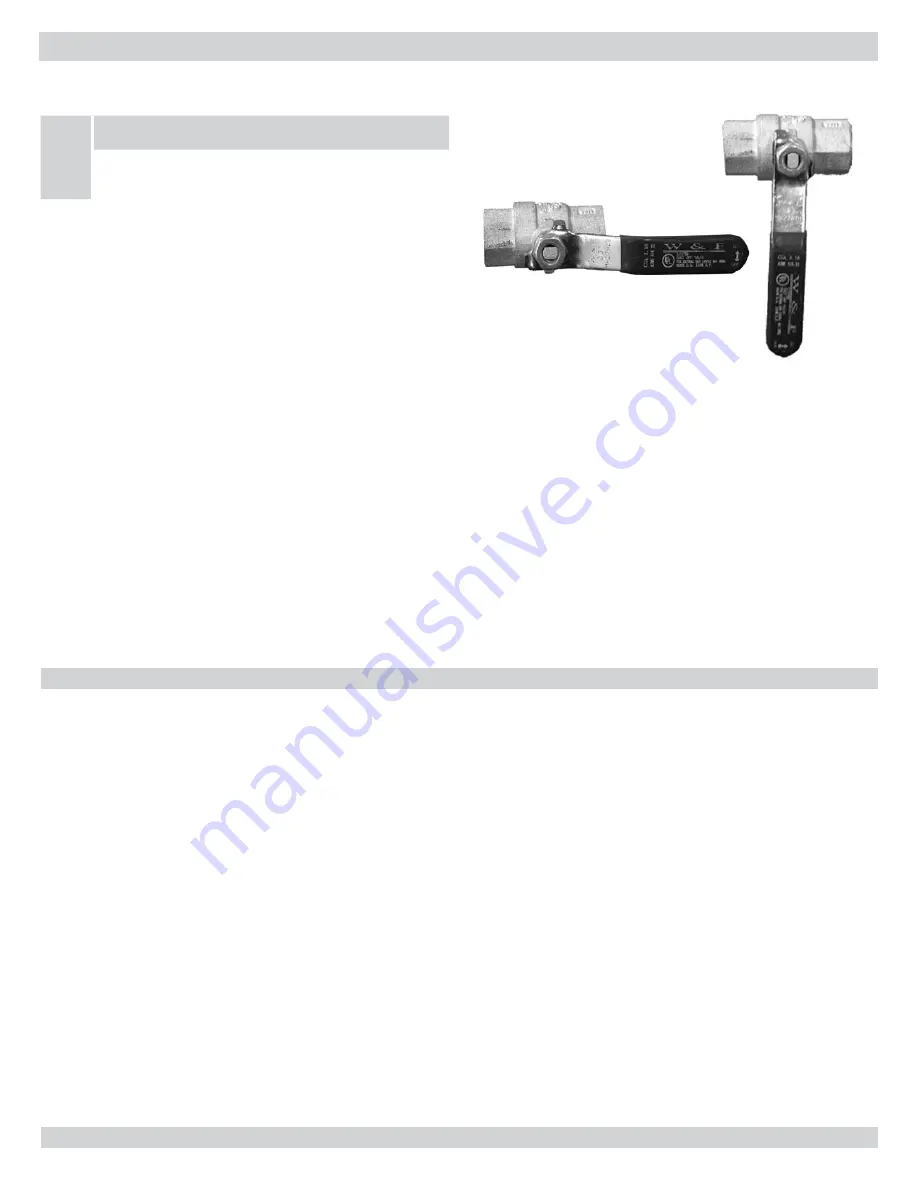
Control Valve “OFF”
Control Valve “ON”
Xiii - puttinG the boiler in operation
to turn off Gas to appliance
Set the thermostat to the lowest setting.
1.
Turn off all electric power to the appliance if service is to be
2.
performed.
Remove the front jacket panel.
3.
Turn gas ball valve off, handle should be perpendicular to the
4.
gas pipe.
Replace the front jacket panel.
5.
Safe lighting and other performance criteria were met with the
6.
gas manifold and control assembly provided on the boiler when
the boiler underwent tests specified in ANSI Z21.13-latest revi-
sion.
operatinG instructions
NOTICE
STOP! Read the safety information above
before operating this appliance.
Set the thermostat to the lowest setting.
1.
Turn off all electrical power to the appliance.
2.
This appliance does not have a pilot. It is equipped with an igni-
3.
tion device which automatically lights the burner. Do not try to
light this burner by hand!
Remove the front jacket panel.
4.
Turn off the gas ball valve. Valve handle should be perpendicu-
5.
lar to the gas pipe.
Wait 5 minutes for any gas to clear. Then smell for gas, includ-
6.
ing near the floor. If you smell gas, STOP! Follow instructions
on this page under “What To Do If You Smell Gas.” If you do
not smell gas, go to next step.
Turn gas ball valve to the “on” position. The handle on the valve
7.
should be parallel to the gas pipe.
Replace the front jacket panel.
8.
Turn on all electrical power to the appliance.
9.
Set thermostat to desired setting.
10.
If the appliance will not operate, follow the instructions “To
11.
Turn Off Gas To Appliance” (below) and call your service tech-
nician or gas supplier.
The acidic nature of flue gases condensing on the aluminum boiler
sections will cause the formation of aluminum oxide. This oxide
formation is normal, is generally uniform throughout the boiler
sections, and represents a negligible mass of aluminum that is con-
sumed by oxidation during the life of the boiler. If left unchecked,
this buildup may eventually cause blockage of the flue gas passages in
the boiler sections, reducing efficiency, and ultimately shutting down
the boiler due to lack of combustion air flow, or drainage of conden-
sate.
Regular service and maintenance by a qualified
service agency must be performed at least once
every 12 months to assure safe, trouble free op-
eration and maximum efficiency.
beginning of each heating season
Schedule an annual service call by a qualified service agency
1.
which includes:
Examining flue passages in the heat exchanger, burner, and
•
condensate lines, and cleaning (if necessary) by following
the instructions in “Annual Examination and Cleaning of
Boiler Components” in this section.
Visually inspecting the venting and air intake system for
•
proper operation, immediately repairing or replacing any
sign of deterioration or leakage, and insuring proper reas-
sembly and resealing of the system.
Checking for and removing any obstruction to the flow of
•
combustion air or venting of flue gases.
Following the instructions in Sections V and VII of
•
the Control Manual and Operating Instructions (P/N#
240006104), “Putting The Boiler In Operation” and
“Checkout Procedures And Adjustments.”
Visually inspecting the condensate drain line for proper
•
operation and checking for deteriorated or plugged con-
densate drain line.
Checking all gasketed joints for leakage and tightening bolts
•
or replacing gaskets as needed.
Removing jacket front and top panels, checking for piping
•
leaks around relief valve and other fittings, and repairing if
found WITHOUT USING stop leak compounds.
Analyze the boiler fluid as instructed in Water Treatment
•
Xiv- maintenance and cleaninG
23
Summary of Contents for UTICA BOILERS UB95M-200
Page 26: ...26 ...
Page 45: ...45 ...
Page 46: ...46 ...
Page 47: ...NOTES ...
Page 48: ...Date Service Performed Company Name Tech Initials Company Address Phone ...


