Route all wires and conduits to the openings in the right jacket
5.
panel.
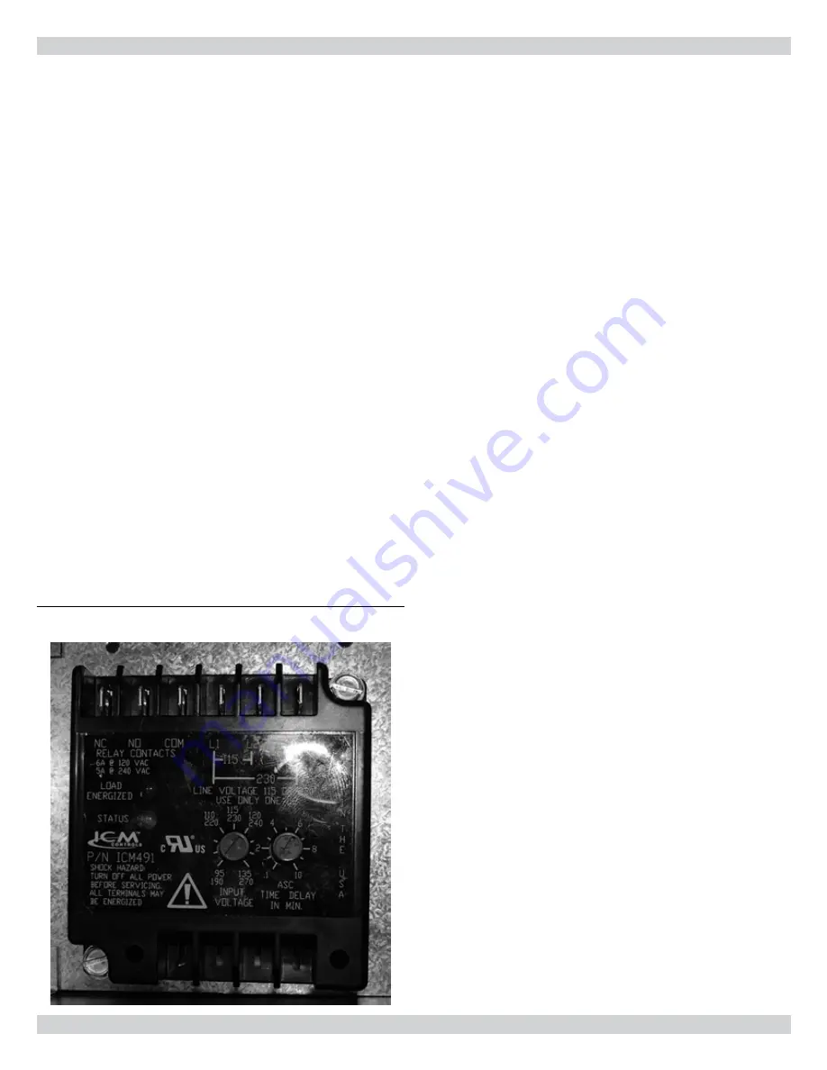
line voltage monitor
This boiler is factory equipped with a line voltage monitor that and
continuously monitors incoming voltage for errors. When incom-
ing line voltage is greater than 12% or less than 8% of the nominal
voltage monitor will flash indicating a fault. Ten minutes after the
line voltage is back within the acceptable range the green light will il-
luminate on the monitor and the boiler will restart. The line voltage
monitor is factory set at 115VAC. It is important that the monitor be
set to the voltage that is present at the installation site by following
these directions:
Using a multimeter, locate the wall outlet nearest to the boiler
1.
and determine the line voltage present on site.
Disconnect power to the boiler.
2.
Remove the boiler cover.
3.
Locate the line voltage monitor mounted to the display panel.
4.
Remove line monitor protective cover.
5.
Using a small screwdriver turn the left dial until the arrow
6.
points at the input voltage measured during step 1.
The right dial should be set at 0.1 minutes, this is the factory
7.
setting.
Reinstall line monitor protective cover.
8.
Replace boiler cover and re-connect power to the unit.
9.
figure 10 - line voltage monitor
low voltage connections
Connect low voltage wiring to low voltage terminal strip as
1.
shown in the boiler wiring diagram.
Route all low voltage wires through opening on the right
2.
jacket panel. Use shielded cable.
thermostat
Connect room thermostat or end switch (isolated contact
1.
only) between terminals T1 and T2.
Install thermostat on inside wall away from influences of
2.
drafts, hot or cold water pipes, lighting fixtures, televisions,
sun rays, or fireplaces.
3. Thermostat anticipator (if applicable):
If connected directly to boiler, set for 0.1 amps.
A.
If connected to relays or other devices, set to match total
B.
electrical power requirements of connected devices. See
device manufacturers’ specifications and thermostat in-
structions for details.
outdoor temperature sensor
Connect outdoor temperature sensor between terminals
1.
A1 and A2 to enable outdoor reset operation of the boiler.
If fixed temperature operation is required, do not install
outdoor sensor.
Mount sensor on exterior wall, shielded from direct sunlight
2.
or flow of heat or cooling from other sources.
If desired, install a summer/winter switch across terminals
3.
A1 and A2. When the switch is closed, the boiler (space
heating) circulator is disabled.
Route sensor wires through the holes provided on the right
4.
jacket panel of the boiler.
dhw aquastat
Connect storage indirect water heater (DHW) aquastat between
terminals DHW T1 and DHW T2.
X - electrical wirinG
16
Summary of Contents for UTICA BOILERS UB95M-200
Page 26: ...26 ...
Page 45: ...45 ...
Page 46: ...46 ...
Page 47: ...NOTES ...
Page 48: ...Date Service Performed Company Name Tech Initials Company Address Phone ...


