


P0031-LI-02.01
25
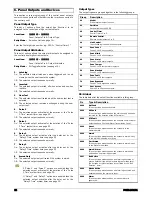
Control Timers
The EC-P8 has five programmable Control Timers, each timer has
a switch on time (On Time), switch off time (Off Time) and days of
operation for both the On and Off times. Control Timer can be
used to automatically arm the system or lock users from
accessing the system. The control timer can also be assigned a
“Link” number, which in turn is used to control “Link Control”
output types, for details on link control, see page 30.
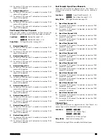
Locations:
3501
to
3505
Control Timers 1 to 5: On Time.
3511
to
3515
Control Timers 1 to 5: Off Time.
Entry Mode:
Number Entry (see page 17).
Enter time in 24hour format, e.g., 1715 = 05.15 PM.
Locations:
3521
to
3525
Control Timers 1 to 5: On Time Days.
3531
to
3535
Control Timers 1 to 5: Off Time Days.
Entry Mode:
Bit Toggle Selection (see page 16).
Options 1 to 7 = Sunday to Saturday.
Locations:
3541
to
3545
Control Timers 1 to 5: Link.
Entry Mode:
Number Entry (see page 17).
Banner Text
This set of options allows you to customise the text that is
displayed on LCD keypads. The “Stay Arm Banners” are shown
when the system has been armed in the relevant stay mode. The
“Keypad Banner” is displayed on the top line when the system is
disarmed. The “Engineer Reset Banner” is displayed on the
bottom line when the system requires an engineer to reset the
system. The top line will always show “Call Engineer”.
Locations:
3601
- Stay Arm 1 Banner.
3602
- Stay Arm 2 Banner.
3603
- Stay Arm 3 Banner.
3604
- Keypad Banner.
3605
- Engineer Reset Banner.
Entry Mode:
String Edit - Text Mode (see page 18).
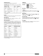
Remote Control Labels
This set of options allows you to customise the text label that is
displayed on LCD keypads for each remote control output. When
the user accesses the remote control output menu, the labels are
displayed, e.g. “Garden Lights”.
Locations:
3621
to
3625
Remote Control 1 to 5: Labels.
Entry Mode:
String Edit - Text Mode (see page 18).
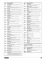
System Links
Each system output can be assigned a “Link” number, which in
turn is used to control the “Link Control” output types, for details
on link control, see page 30.
Locations:
3901
to
3952
System Outputs 01 to 52: Link.
Entry Mode:
Number Entry (see page 17).
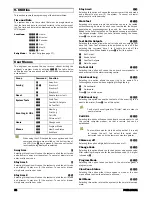
The table below shows the system output types and their
corresponding number 01 to 52. For details of each system
output function, please see page 28.
System Link Types
01 = AC Fault
02 = ATS Fault
03 = System Open
04 = System Armed
05 = System Part Armed
06 = System Armed/Alarm
07 = Bell
08 = Strobe
09 = Intruder Alarm
10 = Confirmed Alarm
11 = Alarm Abort
12 = Fire Alarm
13 = PA Alarm
14 = Duress Alarm
15 = 24hr Alarm
16 = Medical Alarm
17 = Tamper Alarm
18 = Ready for Arming
19 = Trouble
20 = Alert
21 = Bypass
22 = In Walk Test
23 = Flash 1 Second
24 = User Test Active
25 = PSTN Fault
26 = PSTN Off-Hook
27 = PSTN Ringing
28 = Battery Fault
29 = Control Panel Box Tamper
30 = Bell Tamper
31 = Engineer on Site
32 = Detector Reset
33 = Switched 12V
34 = System Low Volts
35 = Exit Mode
36 = Entry Mode
37 = Second Entry Mode
38 = General Alarm
39 = Auxiliary
40 = Warning
41 = Keypads Locked
42 = Output Fault
43 = Engineer Reset Required
44 = Device Fault
45 = Service Requires
46 = Cleaner Bypassed
47 = 2-Wire Smoke
48 = 2-Wire Smoke Alarm
49 = 2-Wire Smoke Fault
50 = Door Access
51 = Alarm Test
52 = Panel AC on
Summary of Contents for EC-P8
Page 1: ...EC P8 8 18 Zone Intruder Alarm System Installation Manual...
Page 4: ...4 P0031 LI 02 01 1 System Overview System Configuration...
Page 45: ...P0031 LI 02 01 45 Notes...
Page 46: ...46 P0031 LI 02 01 Notes...
Page 47: ...P0031 LI 02 01 47 Notes...
Page 48: ...Technical Support Email support zetaalarmsystems com...


