background image

Echoflex Installation Guide

Elaho Preset Station

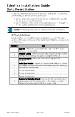
By default, these switches are set to Address 1 and Space 1. Commands
are shared by all devices within a given space.

1. Set the Space rotary switch to the desired number (1 through 16)

for the space you want to control.

2. Set the Address rotary switch to the desired address (1 through 16)

for the station identification in the assigned Space.

Note:

Do not duplicate a device Address within the same space.

DIP Switch Settings

Functionality is set using DIP switches located just beneath the rotary
switches. The label on the rear of the station identifies these components
and functions.

Switch #

Use

1

Use Off - When this is set to Off, the “Off” function of the
station is not provided.

2

Custom Config - When set to On (the default setting), custom
configuration settings are applied using ElahoAccess.

3

Disable IR Input - When On, the infrared input will be
disabled.

4

Fade Time Disable - Applies a 0 second fade time to all station
actions for non-dim switched mode behavior (when dimming
features are not wanted).

5

Future development

6

Future development

7

Future development

8

Restore to Defaults at Boot - Setting this DIP switch On, then
cycling power to the station restores the station to factory
defaults. Reset the switch Off after power cycle.

Elaho Preset Station

Page 3 of 8

Echoflex

Summary of Contents for Elaho Preset Station

Page 1: ...des you through the installation and local configuration of the Preset Station Advanced custom functionality is available using ElahoAccess Custom Configuration For information about the custom config...

Page 2: ...d wiring installation practices Leave approximately 25 4 cm 10 in of wiring in the back box for connection and to allow slack for future service needs Note Echoflex requires that all stations and devi...

Page 3: ...on the rear of the station identifies these components and functions Switch Use 1 Use Off When this is set to Off the Off function of the station is not provided 2 Custom Config When set to On the def...

Page 4: ...g Cat5 careful planning is required to ensure the proper termination kits are available and the wire is pulled appropriately Connect Wiring 1 Pull all required wiring data data and an additional 2 5 m...

Page 5: ...nstall the Station in the Back box Note For some flush mount applications with certain trim rings it may be necessary to remove the station s back cover for insertion into the back box 1 3 2 4 1 Inser...

Page 6: ...ceplate on the tabs located on the top of the station electronics assembly To ensure the faceplate is hooked properly on the top hook wiggle it slightly side to side while the bottom is angled 20 degr...

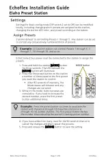
Page 7: ...s The LED beneath the MODE button will illuminate 2 Press the first preset button on the station a number of times equal to the first preset you want the station to control After 90 seconds of inactiv...

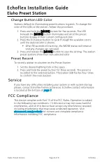
Page 8: ...ord To record a preset to a button on the Preset Station 1 Set the desired lighting look in the space 2 Press and hold the preset button for three seconds The preset is recorded to the selected button...

Reviews: