background image

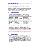
EchoMap v3.0 

11


2.5.1


Satellite Indicator Colors 

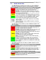
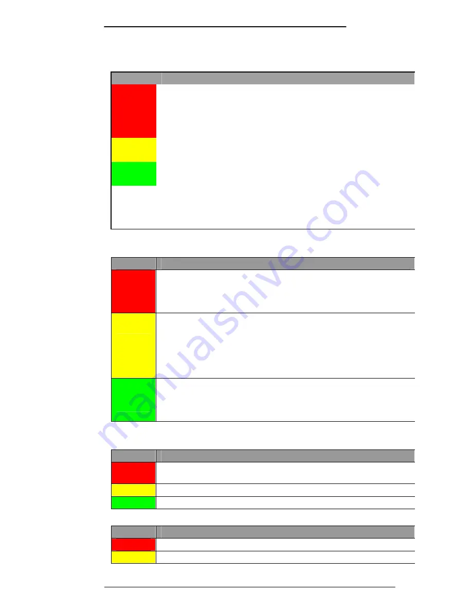
The ORBCOMM status indicator shows whether you have established a 

link with the satellites and whether you are transmitting or receiving. 

Color 

ORBCOMM Satellite Indications

  (upper left) 

Red 


No signal is being received on the serial port or the satellite 

transceiver has failed its initial check and verification.   

Remedy:

 Confirm that the satellite transceiver is receiving 

power and is connected securely to the computer’s serial port 

using the provided serial cable.  

Yellow 


The satellite transceiver is operating correctly and is ready to 

receive or transmit data, but no ORBCOMM satellite is in view. 

Green 


You are currently in view of an ORBCOMM satellite.  Dotted 

Green and Red bars indicate Signal Strength and Noise. 

White 

arrow 

Arrow pointed up means satellite transceiver is transmitting 

data to satellite. 

Arrow pointed down means satellite transceiver is receiving 

data from satellite. 

The GPS indicator shows whether you have established reception of the 

GPS constellation. 

Color 

GPS Lock Indications

  (lower left) 

Red 


No signal is being received from the satellite transceiver or it 

has failed its initial check and verification.  

Remedy:

 Confirm that the satellite transceiver has power and 

is securely connected to the computer’s serial port.  

Yellow 


GPS signal is being received, but the GPS receiver has not yet 

locked on to at least three satellites. 

Remedy:

 If the GPS indicator remains yellow, double-check 

the GPS antenna connection and placement. 

Note:

 The first time the system is used, the GPS may take 

some time to lock on. 

Green 


Locked on to at least three satellites with good geometry, 

providing real-time position for the moving map.  If you are 

using a WAAS GPS, a WAAS lock is indicated by “WAAS” black 

text on green. 

The Weather indicator shows the status of weather requests as well as 

the age of weather

.  

Color 

WX Status Indications

  (upper right) 

Red 

Current weather is over an hour old, or Demo weather 

displayed. 

Yellow 

A request for weather has been made but not yet received. 

Green 

Weather under an hour old displayed. Shows the age. 

The message indicator shows the status of message requests. 

Color 

Message Status Indications

  (lower right) 

Red 

No queue count available from satellite transceiver. 

Yellow 

Messages are queued to send.  

Summary of Contents for EchoMap 3.0

Page 1: ...EchoMap 3 0 User s Guide 1919 14 th St Suite 601 Boulder Co 80302 Customer Support 1 888 739 7161 Support EchoFlight com www EchoFlight com...

Page 2: ...s Manual is for users of EchoMap on an Echo Flight Flight Cheetah Multi Function Display or a Windows laptop An electronic version of this manual will be installed to Echomap Docs EchoMapGuide pdf 1 2...

Page 3: ...has been removed altitude information should not be used for vertical navigation This system is for portable use Please observe all FAA regulations including 91 21 regarding the use of portable equipm...

Page 4: ...3 5 Terrain Contour 16 3 5 1 Display the Terrain Contour Overlay 16 3 5 2 Display Black Background 16 3 6 Terrain Tower Alerts 16 3 6 1 Terrain Alert Indicator 17 3 6 2 Tower Alert Indicator 17 3 6 3...

Page 5: ...r 34 6 1 2 Exit to Windows laptop computers only 34 6 1 3 Update from CD 34 6 1 4 System Settings Menu 35 6 1 5 System Diagnostics Menu 35 6 1 6 Minimize laptop computers only 35 7 DATA LINK Weather 3...

Page 6: ...l 51 8 1 How to Send Email 51 8 2 Receiving Email 52 8 2 1 Email Login 53 8 3 Position Reporting 53 9 The ORBCOMM Data Link Network 54 9 1 Advantages of LEO Technology 54 9 2 Network Operation 55 9 2...

Page 7: ...abytes 1 gigabyte or more Ports 1 serial or USB port 2 serial or USB port At least one RS 232 serial port is required to communicate with the Satellite Transceiver and or GPS Receiver USB to Serial ad...

Page 8: ...of six separate sections 1 Heading information upper left panel 2 Obstacle Alert second down on left 3 Direct to location third down on left 4 Position information lower center left panel 5 GPS and OR...

Page 9: ...to a maximum deflection of 11 degrees Navigation is as simple as flying towards the triangle 2 2 Obstacle Alert Indicator The obstacle alert indicator panel will automatically display either a tower...

Page 10: ...ss When GPS reception is less than 4 satellites no altitude is displayed and you will receive a No Alt warning in the Obstacle clearance panel Note Although government Selective Availability has been...

Page 11: ...Indications lower left Red No signal is being received from the satellite transceiver or it has failed its initial check and verification Remedy Confirm that the satellite transceiver has power and i...

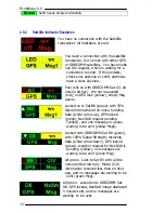
Page 12: ...ellow empty Msg queue Locked on to Sat B8 green with 70 Signal Strength and no noise Sending data white arrow up GPS locked green NexRAD request pending yellow and one message in queue waiting to be s...

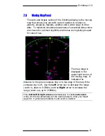
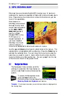
Page 13: ...e logically grouped for ease of use The map range is displayed in the upper right corner of the moving map It indicates the distance to the green compass ring or to top edge of the map if the compass...

Page 14: ...ess to menus Use the up and down arrow keys to select items in the menus The selected item is highlighted with a yellow bar Press the Enter key to activate the selected item You can close the menu by...

Page 15: ...ht it is suggested you operate the display in demo mode To operate in demo mode First press the Nav key Then scroll down to GPS Settings and press Enter Next scroll down to Demo and press Enter 3 3 Ma...

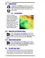
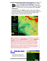
Page 16: ...uth 3 5 1 Display the Terrain Contour Overlay Press the Nav button select Terrain In the Terrain menu select Map ON and Mode Map Next press Enter to remove the menu You can toggle this function on and...

Page 17: ...levation data The terrain database is derived from the USGS GTOPO30 global digital elevation model DEM Elevations are regularly spaced at 30 arc seconds about 1 Km Elevations are stored in 100ft incre...

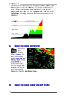
Page 18: ...00 1000 feet are in yellow and 1000 feet 1500 feet green Anything in excess of 1500 feet clearance is not displayed 3 7 Display The Terrain Alert Overlay Press the Nav button select Terrain In the Ter...

Page 19: ...d and is strictly for supplemental use only Even with increased accuracy since the termination of selective availability GPS altitude still varies above and below the actual altitude by several hundre...

Page 20: ...ince it displays distance to ring If compass ring is turned off map range indicator displays the distance from the current position to the top of the screen 3 9 2 Display Course Lines The Course Line...

Page 21: ...igured you can quickly change between them by pressing the Up and Down arrow keys from the moving map You can create as many separate data pages as you wish The system comes with several layers precon...

Page 22: ...rectional Beacons INT I Intersections VOR V VHF Omni directional Radio range AWY W Low Altitude Airways JWY J Jet Airways ARR R Arrivals DEP D Departures PJA P Parachute Jump Areas OBS O Obstructions...

Page 23: ...nu allows you to set the distance ahead of your aircraft that you want this type of navaid to be displayed The Zoom setting is the range in miles as shown in the upper right hand corner of the moving...

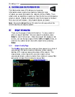
Page 24: ...target waypoint 4 1 Airport Information There are five pages of airport information To view select or enter an airport identifier Once an airport is selected press Enter to view it full screen When t...

Page 25: ...he airport including Tower Approach Departure ATIS GND Unicom and others 4 1 3 Airport Map Page The map page displays a map of the airport and landmarks around the facility The map shows terrain runwa...

Page 26: ...ates subscription Echo Flight Plan3 or Plan4 will have these NOS plates If you aren t already in full screen mode press Enter Use the Up and Down arrows to select the chart and press Enter to display...

Page 27: ...EchoMap v3 0 27...
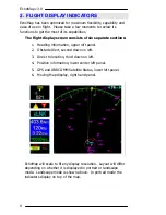
Page 28: ...ation pages display the Name Frequency and Elevation of each VOR Arrow down to highlight the VOR 4 3 NDB Info Page NDB information pages display the Name Frequency and Elevation of each NDB Arrow down...

Page 29: ...oints either select a point by scrolling through the list on the left hand side of the screen with the Down arrow or manually enter its name with the Up and Down arrows similar to the way you would sc...

Page 30: ...the Longitude and Latitude values automatically The waypoint will be displayed as a thin green cross on your map Once you have the desired position entered you must select Add Waypoint for the point...

Page 31: ...w to activate the edit box then use the Up and Down arrow keys to cycle through the alphabet When the desired letter is reached use Right arrow again to go to next position When the identifier is comp...

Page 32: ...ifier are characters to indicate the type of approach overlays available in the database for that runway You can select a runway from the list or you can skip the runway selection by pressing Enter at...

Page 33: ...button will directly display the associated approach plate scan instead of the normal Info Menu Pilots should always verify the accuracy of the approach displayed on the GPS map against the plate scan...

Page 34: ...p computer users are given the option to Exit the EchoMap software to Windows without turning off the computer If FL240 or 270c users need to exit to Windows they must have started the computer with a...

Page 35: ...ity to run in landscape or portrait mode Use Rotate Display from the System Settings menu to toggle between landscape and portrait mode 6 1 5 System Diagnostics Menu This menu is only necessary when E...

Page 36: ...EchoMap v3 0 36 You can also toggle between windowed and full screen modes by pressing F10 on a keyboard...

Page 37: ...xRAD images are updated on average every 5 minutes and the average age of EchoMap Data Link Weather typically ranges between 5 to 10 minutes by the time it reaches the cockpit Data Link Weather enable...

Page 38: ...0 38 Correct way to Use Data Link Weather Incorrect way to use Data Link Weather Note The Airman s Information Manual recommends that pilots should circumnavigate inclement weather by at least 25 naut...

Page 39: ...s near real time typically no more than 5 10 minutes old on average but not instantaneous and should never be used for tactical weather avoidance It should be used for strategic weather avoidance only...

Page 40: ...e weather update returned to you greatly depends on when your request arrives at the Echo Flight Network Center For instance your request might arrive 4 minutes after the update was posted It takes ro...

Page 41: ...e diameter of the weather request area Use the Left and Right keys to decrease or increase the range from 75 and 500 Nm in 25 Nm increments In order to optimize your request select only the range you...

Page 42: ...eful when looking ahead over long distances Select Request Point in the menu and select the desired point as you would if you were flying direct to that target see section 4 6 Once you select an item...

Page 43: ...120 heading at slightly more than 100 and 200 nautical miles away The closer you are to the precipitation the more detail the cell patterns will provide The further the activity is from you the less...

Page 44: ...rate to heavy rain or heavy snow possible lightning 0 06 to 1 5 rain hr or 0 5 to 1 snow hr 30 54 dbz R Re ed d Extreme rain sleet hail lightning 2 5 rain hr or sleet hail 55 dbz WARNING You should al...

Page 45: ...ge is displayed by the WX status indicator You can cycle through these pages of Metar data by pressing Enter from the moving map To request a graphical Metar report for all the airports in your area p...

Page 46: ...to 1 000 ft Less than 3 NM LIFR Less than 500 ft Less than 1 Nm 7 4 3 How to Read Precipitation Levels Inside the L shaped Ceiling Visibility bars may be letters indicating precipitation If there is n...

Page 47: ...with moderate rain reported with the age of the report 30 60 minutes AMG has a low IFR ceiling and low IFR visibility and heavy snow reported with the age of the report 30 60 minutes VLD has a margin...

Page 48: ...d The Wind layer shows the wind speed and direction on the ground at the airport The speed is shown as a range with a possible gusting value Wind direction is drawn using a T shaped bar With the wind...

Page 49: ...spread Yellow between 7 10 degrees Red 6 degrees or less 7 4 8 How to View Weather Overlays There are five weather overlay options that you can scroll through in flight with the Enter key including o...

Page 50: ...irport enter the identifier or select from the list Once you select an airport press Enter to send the request When the report is received a bar will appear above the moving map telling you a Metar re...

Page 51: ...e fields If you do not have a keyboard to enter text into these fields you must use the arrow keys to set the letters Enter a TO address or select a previously used one Addresses you enter manually wi...

Page 52: ...ton or Delete on a keyboard Use the Reply option to reply to the selected Email Your satellite transceiver is provisioned at Echo Flight to have an Email address like EFlight59 EchoFlight net Your Ech...

Page 53: ...figure alternate Email addresses that messages sent to your in flight address will forward to when you are not logged in 8 3 Position Reporting Position reports can be sent manually or automatically T...

Page 54: ...es above the Earth The close proximity to earth means the Subscriber Communicators require less powerful transmitters 5 watts and relatively simple whip antenna systems Therefore the transceiver equip...

Page 55: ...portable computer 9 2 1 Space Segment The main function of the ORBCOMM satellites is to complete the link between the Subscriber Communicator SC and the switching capability at the NCC in the U S The...

Page 56: ...is responsible for managing the ORBCOMM network elements and the U S gateways through telemetry monitoring system commanding and mission system analysis It provides network management of ORBCOMM s sat...

Page 57: ...f the Satellite Communicator the flight computer and the antennas Subscriber Communicator SC The SC is a two way transceiver that provides in flight access to weather messaging and position reporting...

Page 58: ...hield of the aircraft and a special VHF antenna mounted on the top of the fuselage for two way communications with the ORBCOMM satellites The VHF antenna is the only permanent installation required Re...

Page 59: ...within normal parameters contact support at Echo Flight If you have Email we may ask you to send these files to us for review 10 2 Disk Space It is recommended that you always have at least 10 megaby...

Page 60: ...D Demo Toggle demo movement Won t work if GPS is on Ctrl G GPS Toggle GPS movement scanning for SC if necessary Ctrl K Keyboard Mode Toggle keyboard mode Ctrl Q Clear queues Clears the send and recei...

Page 61: ...flight path line display V VORs Toggle VOR display W Victor Airways Toggle victor airway display Y Hydro Toggle hydro graphics display or Zoom In Reduce the scale of the map or Zoom Out Increase the s...

Page 62: ...the ORBCOMM satellite to provide a direct link to the ORBCOMM Network Control center GS Ground Speed Speed of travel across the ground measured in nautical miles per hour INT Intersection Intersection...

Page 63: ...distance from the aircraft this is user configurable NDBs closest to furthest can also be accessed directly through the D F5 and INFO F2 keys Rng Range The distance from the present position to the d...

Reviews: