background image

Page 2 of 7

Installation & Mounting:

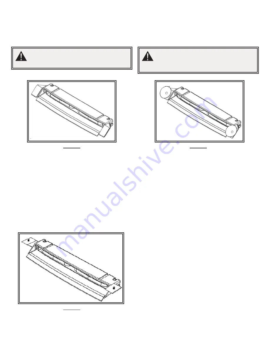
Note: Image shown is a ED5051VDL2 product.  Use the same installation & mounting instructions for ED5051VDL1 product series.

Carefully remove the unit from its packaging. Examine the unit for transit damage. If damage is found, return the product to your local 

dealer for warranty replacement. Do not use damaged or broken parts. Determine a mounting location that ensures a clear line of sight for 

oncoming traffic.

CAUTION!

When drilling into any vehicle surface, make sure that the 

area is free from any electrical wires, fuel lines, vehicle 

upholstery, etc. that could be damaged.

Mounting with Shroud:

Figure 1

Figure 2

Mounting with Shroud:

1.  Ensure that the light head is securely attached to the shroud.

2.  Install rubber gasket onto the shroud.

3.  Remove the suction cup from each shroud bracket.  

4.  Clean the brackets with supplied alcohol wipe. * for extra adhesion, see 

notes below.

5.  Remove one side of the adhesive liner & apply to both brackets. Apply 

light pressure for 20 seconds.

6.  Install the bracket as shown on Figures 4 & 5.  Gently hand tighten the 

nut.

7.  WITHOUT removing the second adhesive liner, hold the product to 

desired location. Loosen & hand tighten the nut as needed to adjust 

the light head angle. Once desired angle is achieved, gently tighten the 

fastener using a 10mm wrench or socket. 

8.  Clean mounting surface with supplied alcohol wipe. *for extra adhesion, 

see notes below.

9.  Remove the second adhesive liner.

10. Apply product on to the treated surface. Apply light pressure for 20 

seconds.

Mounting with Suction Cup:

1.  Ensure that the light head is securely attached to the shroud.

2.  Install the shroud bracket as shown on Figures 4 & 5.  Gently hand 

tighten the nut.

3.  Clean mounting surface with supplied alcohol wipe.

4.  Apply the product on to the treated surface by gently pressing the suction 

cups on to the glass. Apply light pressure for 20 seconds. Gently adjust 

the light head to its desired angle if needed.

5.  Once desired angle is achieved, gently tighten the fastener using a 10mm 

wrench or socket.

*For extra adhesion, use 3M Tape Primer. For product & application information, go to:

https://multimedia.3m.com/mws/media/65952O/3mtm-tape-primer-94.pdf

Mounting with Hardware (NOT PROVIDED):

1.  Ensure that the light head is securely attached to the shroud.

2.  Install the shroud bracket as shown on Figures 4 & 5.  Gently hand 

tighten the nut.

3.  Clean mounting surface with supplied alcohol wipe.

4.  Install product on to the treated surface by using #8 hardware screw (not 

included). Torque screws to 8 ± 2 in-lbs.

5.  Gently adjust the light head to its desired angle if needed.

6.  Once desired angle is achieved, gently tighten the fastener using a 10mm 

wrench or socket.

CAUTION!

When installing using VHB tape into any vehicle with 

aftermarket tinted glass, it is best practice to trim the 

film around the surface where bracket will be mounted to ensure 

adhesion and avoid damage to the tint film.

** MOUNTING HARDWARE NOT PROVIDED

Figure 3

Summary of Contents for ED5051VDL Series

Page 1: ...ximized and the controls are placed within convenient reach of the operator so that they can operate the system without losing eye contact with the roadway 5 Do not install this product or route any w...

Page 2: ...or extra adhesion see notes below 9 Remove the second adhesive liner 10 Apply product on to the treated surface Apply light pressure for 20 seconds Mounting with Suction Cup 1 Ensure that the light he...

Page 3: ...ve the suction cups from the shroud mounting brackets 3 Install each suction cup to each bracket using the existing screws as shown on Figure D 4 Insert bracket as shown on Figure B 5 Clean mounting s...

Page 4: ...y default pattern 5 secs last pattern Dimming Function Connect blue wire to Red power wire Synchronization The ED5051VDL series is capable of syncing with other compatible ECCO products by following t...

Page 5: ...olor 2 A 120 CLASS 1 N A 17 Double Flash Color 2 B 120 CLASS 1 N A 18 18 Double Flash Alternating Color 1 Color 2 A 120 N A N A 19 19 Double Flash Alternating Color 1 Color 2 B 120 N A N A 20 20 Doubl...

Page 6: ...multaneous Color 2 B 120 Class 1 Class 1 N C N C 35 Double Flash Alterna ng Color 2 A 120 N C N C N C N C 36 Double Flash Alterna ng Color 2 B 120 N C N C N C N C 37 Single Flash Simultaneous Color 1...

Page 7: ...WARRANTIES FOR MERCHANTABILITY OR FITNESS FOR A PARTICULAR PURPOSE ARE HEREBY EXCLUDED AND SHALL NOT APPLY TO THE PRODUCT BUYER S SOLE AND EXCLUSIVE REMEDY IN CONTRACT TORT OR UNDER ANY OTHER THEORY A...

Page 8: ...perador del veh culo asegurarse de que todas las caracter sticas de este producto funcionan correctamente durante su uso Durante su uso el operador del veh culo debe asegurarse de que no haya componen...

Page 9: ...es notas 9 Retire el segundo recubrimiento del adhesivo 10 Aplique el producto sobre la superficie tratada Presione suavemente durante 20 segundos MONTAJE CON VENTOSA 1 Aseg rese de que el cabezal de...

Page 10: ...ntosas de los soportes de montaje de la cubierta 3 Instale cada ventosa en cada soporte con los tornillos existentes como se muestra en la Figure C 4 Inserte el soporte como se muestra en la Figure B...

Page 11: ...incronizaci n relativa entre las unidades conectadas en una instalaci n en sincronizaci n Para operar simult neamente cada unidad debe configurarse en la misma fase A A o B B para funcionar de manera...

Page 12: ...P gina 5 de 6 SELECCIONAR PATR N ENCENDIDO COLOR 2 APAGADO ENCENDIDO COLOR 1 Selecci n de patr n de parpadeo Adaptador de cigarrillos...

Page 13: ...UIER SUPUESTO EN CONTRA DEL FABRICANTE RESPECTO AL PRODUCTO Y SU USO SER EL REEMPLAZO O LA REPARACI N DEL PRODUCTO O EL REEMBOLSO DEL PRECIO DE COMPRA PAGADO QUE HAYA PAGADO EL COMPRADOR POR EL PRODUC...

Page 14: ...la s curit de tous les passagers l int rieur du v hicule en vitant en particulier les zones d impact potentiel de la t te 6 Il incombe l op rateur du v hicule de s assurer que toutes les fonctionnalit...

Page 15: ...mentaire voir les notes ci dessous 9 D poser le deuxi me film adh sif 10 Appliquez le produit sur la surface trait e Appliquez une l g re pression pendant 20 secondes MONTAGE AVEC VENTOUSE 1 S assure...

Page 16: ...s supports de montage de d flecteur 3 Installer chaque ventouse sur chaque support l aide des vis existantes comme indiqu la Figure C 4 Ins rer le support comme indiqu la Figure B 5 Nettoyez la surfac...

Page 17: ...au indiquent la synchronisation relative entre les unit s branch es dans une installation synchronis e Pour fonctionner simultan ment chaque unit doit tre r gl e sur la m me phase A A ou B B pour fonc...

Page 18: ...P gina 5 de 6 S LECTION DE MOD LE ON COULEUR 2 DE ON COULEUR 1 S lection du mod le de clignotement ADAPTATEUR CIGARETTE...

Page 19: ...OUTE AUTRE TH ORIE EN CE QUI CONCERNE LE PRODUIT ET SON UTILISATION SE LIMITERONT LA DISCR TION DU FABRICANT AU REMPLACEMENT OU LA R PARATION DU PRODUIT OU AU REMBOURSEMENT DU PRIX D ACHAT PAY PAR L A...

Reviews: