ROTATION FROM CENTER
0
240
-240
R
ES
IS
TA
N
C
E
FO
R
C
E
0
M
A
X
MINIMUM PRELOAD
ROTATION FROM CENTER
0
240
-240
R
ES
IS
TA
N
C
E
FO
R
C
E
0
M
A
X
MAXIMUM PRELOAD
OUTER
MIDDLE
INNER
140 lb.
173 lb.
197 lb.
197 lb.
24 lb.
57 lb.
116 lb.
2.0 TURNS MAX PRELOAD
2.0 TURNS MAX PRELOAD
2.5 TURNS MAX PRELOAD
57 lb.
81 lb.
116 lb.
2.5 TURNS MAX PRELOAD
3.0 TURNS MAX PRELOAD
3.5 TURNS MAX PRELOAD
MONOPOINT II
CONCENTRIC
SPRING SYSTEM
2.0 TURNS FOR STRONGEST CENTERING FORCE
0.75 TO 1.25 TURNS FOR BALANCED FEEL
0.5 TURNS FOR LIGHTEST CENTERING
2.0 TURNS FOR STRONGEST CENTERING FORCE
0.75 TO 1.25 TURNS FOR BALANCED FEEL
0.5 TURNS FOR LIGHTEST CENTERING
2.5 TURNS FOR STRONGEST CENTERING FORCE
1 TO 1.5 TURNS FOR BALANCED FEEL
0.5 TURNS FOR LIGHTEST CENTERING
2.5 TURNS FOR STRONGEST CENTERING FORCE
1 TO 1.5 TURNS FOR BALANCED FEEL
0.5 TURNS FOR LIGHTEST CENTERING
3.5 TURNS FOR STRONGEST CENTERING FORCE
2.0 TO 2.5 TURNS FOR BALANCED FEEL
0.75 TURNS FOR LIGHT CENTERING
SPRING COMBINATIONS
PRELOAD RANGE AVAILABLE
3.0 TURNS FOR STRONGEST CENTERING FORCE
1.5 TO 2 TURNS FOR BALANCED FEEL
0.75 TURNS FOR LIGHT CENTERING
BALANCED RANGE IS RECOMMENDED FOR THE BEST COMBINATION OF SMOOTHNESS AND CENTER FEEL
COMBINATION
TRACKSTAR
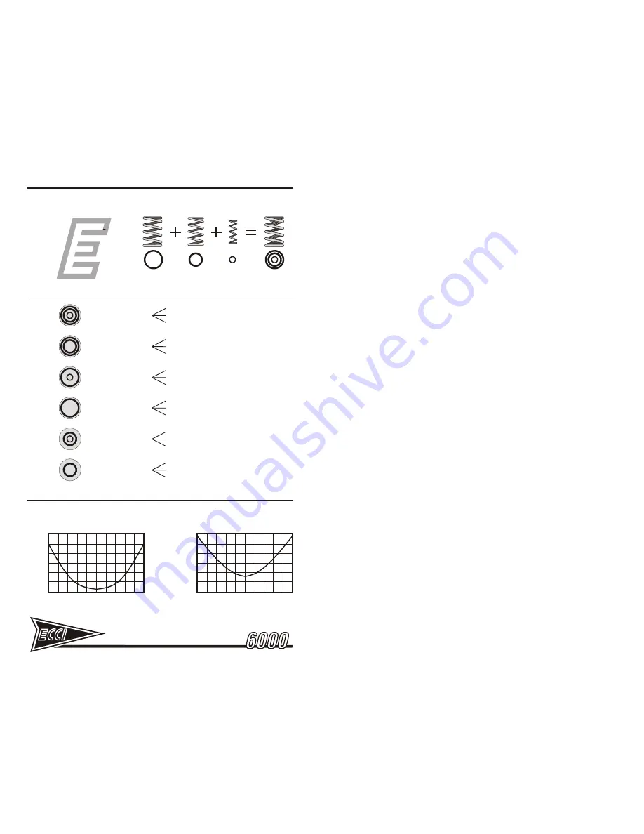
Figure 24 - STEERING RESISTANCE SPRING COMBINATIONS
Figure 25 - STEERING CENTERING TUNING
1
WARNING! Do not exceed the maximum number of turns listed in the table
for the combination of springs being used – excessive pressure will damage
the steering camshaft. Exceeding the recommended number of turns is
considered MISUSE and damage from misuse is NOT covered under
warranty! Be careful!
2
Tighten the preload adjuster locknut, while holding the preload adjuster
screw in position with the hex key wrench.
Note: If the springs the springs make noise after installation, examine the
assembly to make certain that all springs are seated properly in their respective
pockets, both in the upper and lower spring retainer. Most noise issues are
caused by the large outer spring not being rotated against the spring stop screw
[Figure 22].
3.6
FLDS - FLUID DAMPED STEERING
The FLDS system uses a belt driven rotary fluid damper [Figures 6 & 26]. For
each wheel rotation the damper will rotate multiple times. The damping ratio
provided standard with the Trackstar 6000 provides a balance of damping and
spring resistance. Some users may wish to reduce or increase the amount of
damping. ECCI offers pulleys in several different ratios for purchase [Figure 27].
Generally, someone who uses many rapid wheel movement corrections while
driving may prefer a lighter pulley, while someone using very steady measured
wheel movements may prefer even heavier damping.
Steering wheel diameter also has an effect on damping force. Diameters smaller
than the standard 13-1/2 inch wheel will create less leverage on the steering
shaft. This will increase the level of damping perceived by the driver.
3.7
SHIFT PADDLE ADJUSTMENT
The Trackstar 6000 unit is provided with F-1 style behind-the-wheel paddles to
perform gear shift function. The paddles have a very short throw to make rapid
shifting possible. However, there is a small range of adjustment. The factory
setting provides a moderate amount of tolerance for the switch actuation point. If
throw adjustment needs to be reset, the stop screws can be adjusted with a hex
key and 3/8 in. wrench. If any button or paddle control remains on constantly or
does not trigger except at the very end of travel, adjustment will be needed.
Sometimes the switches will ‘wear in’ to a different engagement point than when
new and require readjustment after a period of time.
Depending on which steering wheel you have, stops may be located at the back
and in some cases the front of each paddle. Before making adjustments, make
sure the wheel and paddles are bolted tight to the steering hub. Unless
compressed in place by the steering wheel, paddle components may warp
slightly affecting the accuracy of the adjustment.
Before adjusting, loosen the locknuts of the stop screws with a 3/8” wrench. Find
the control trigger point with a continuity tester or by leaving the unit plugged in to
your computer and set to a calibration utility. When the trigger point is found, turn
the stop screws in gradually to ‘bracket’ this point to the desired tolerance. Be
careful to not adjust travel too close to the actuation point, for inconsistent
shifting operation may result. When finished make sure to tighten the locknuts to
ensure that the stop screws are securely locked in place.


