background image

XRGI

®

- INSTALLATION GUIDE

 VERSION 1.0 2018

52

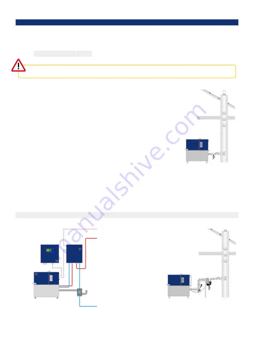
C O N D E N S I N G   E X H A U S T   
G A S   H E AT   E X C H A N G E R

to the Storage Tank

from the Storage Tank

5.2  

E X H A U S T   G A S   S I D E   I N S TA L L AT I O N

5.2.1    E X T E R N A L   E X H A U S T   H E AT   E X C H A N G E R 

E x h a u s t   g a s   c o n n e c t i o n   o n   t h e   P o w e r   U n i t 

X R G I ®   6 / 9 / 1 5 / 2 0 

DN 60

Discharge the exhaust gases from the Power Unit through an exhaust gas pipe. Install the exhaust gas system in accordance with 
regulations applicable in the country of installation. 

Make sure that the fresh air intake and the exhaust gas pipes comply with installation 
type B (room air dependent). Only permit a qualified fitter to connect up the system. 
The installation regulations of the exhaust system manufacturer are to be observed.

The Power Unit is not designed for condensing operation, nevertheless install a conden-
sate drain to trap and discharge any condensation produced when the system starts 
up. Fit a condensate box with a large water reserve or a trap with a ball valve or similar 
to prevent the condensate drain from drying out. Use exhaust gas lines that comply 
with temperature class T160 or higher, since the exhaust gas temperatures involved are 
continuously close to the permissible limit and the XRGI® system mainly runs for long 
periods of time.

Make sure that the exhaust gas system is pressure-tight (pressure-resistant to 5,000 Pa, 
type H1 or H2). Do not route condensate and exhaust gas pipes horizontally. Ensure that 
they have a minimal gradient of 5% to allow the condensate to run off. Make sure that 
the length of the exhaust gas line, with an internal diameter of 80 mm and up to five 
bends, does not exceed 20 metres. Extrapolate in line with EN 13384 as required if there 
are more than five bends or if the pipe is longer.

In principle, each XRGI® system needs a separate exhaust gas pipe. Exhaust gas pipes can be cascaded from the Power Unit side, but 
the exhaust pipe must be approved for this purpose by the manufacturer. You may have to extrapolate the pressure conditions in line 
with EN 13384. 

You can add an external exhaust heat exchanger to the Power Unit to improve its thermal efficiency. However, a notable increase 
in output can only be achieved in condensing operation. The return temperatures from the heating system should permanently lie 
below 45 to 50 °C. After the external exhaust heat exchanger, flue pipes with approval 120 ° C (PP) are permitted. 

Ensure that the exhaust gas pipe is gas-tight. Comply with all national fire regulations!

Fig. 5.18 – Assembly example

Fig. 5.16 – Assembly example

Fig. 5.17

Summary of Contents for XRGI 15

Page 1: ...I N S T A L L A T I O N G U I D E 01DOC1043 VERSION 1 0 2018 FOR PROFESSIONALS ...

Page 2: ... 1 1 SAFETY AND WARNING SYMBOLS USED 22 3 2 INTENDED USE 22 3 3 GENERAL SAFETY INSTRUCTIONS 24 3 3 1 HANDLING ENGINE OIL 24 3 3 2 ACTIONS WITH SMELL OF GAS IN BUILDINGS 25 3 3 3 ACTIONS WITH FIRE OR IGRESS OF WATER 25 3 3 4 ACTIONS WITH SMELL OF EXHAUST GAS IN BUILDINGS 25 3 3 5 FROST PROTECTION 26 3 3 6 CONTACT HAZARD 26 3 3 7 EXPLOSIVE AND EASILY FLAMMABLE MATERIALS 26 3 3 8 COMBUSTION AIR SUPPL...

Page 3: ... 1 HYDRAULIC INSTALLATION 45 5 1 1 EC POWER STANDARD HYDRAULIC SYSTEM 45 5 1 2 INSTALLATION Q HEAT DISTRIBUTOR POWER UNIT 49 5 1 2 1 PRIMARY CIRCUIT FLOW AND RETURN CONNECTION 49 5 1 3 INSTALLATION Q HEAT DISTRIBUTOR STORAGE TANK CONSUMER NETWORK 50 5 1 3 1 SECONDARY CIRCUIT FLOW AND RETURN CONNECTION 50 5 1 3 2 EC POWER STORAGE TANK 51 5 2 EXHAUST GAS SIDE INSTALLATION 52 5 2 1 EXTERNAL EXHAUST H...

Page 4: ...ocuments must be followed EC POWER cannot take responsibility for any damages caused by non compliance with the instructions for the XRGI system 1 1 O R I G I N A L O P E R AT I N G I N S T R U C T I O N 1 2 A P P L I C A B L E D O C U M E N T S 1 3 K E E P T H E D O C U M E N T S 1 4 S YM B O L S U S E D 1 5 R AT I N G P L AT E This XRGI installation guide contains original operating instructions...

Page 5: ...ed on the inside of the iQ Control Panel door and on the left side of the iQ Control Panel below the main switch disconnector Legend 1 iQ Control Panel serial no 2 Technical data of the iQ Control Panel 3 Type description of the iQ Control Panel 4 XRGI ID of the XRGI system 1 7 C E M A R K I N G 1 6 VA L I D I T Y O F T H E G U I D E This XRGI installation guide only applies to XRGI systems with t...

Page 6: ...ing to current demand Service and error messages in the heating system 2 S YS T E M CO M P O N E N T S 2 1 M A I N X R G I S YS T E M CO M P O N E N T S An XRGI system consists of three main components the Power Unit the Q Heat Distributor and the iQ Control Panel The XRGI system can be expanded with additional XRGI accessories Storage Control Boiler Control Flow Master Control Flow Master Electri...

Page 7: ...insulated engine compartment 1 Silencer integrated 2 Water cooled generator 3 Exhaust gas cooler not visible 4 Oil sump 5 EC POWER gas engine 6 Oil separator 7 Catalyst not visible patented 8 Primary circuit flow 1 G 9 Primary circuit return 1 G 10 Electrical connection 11 Exhaust gas connection twin tube di 60 mm da 100 mm 12 Gas connection G 13 Air filter 14 Gas safety circuit 15 Cover with gas ...

Page 8: ... gas connection twin tube di 60 mm da 100 mm 12 Gas connection XRGI 15 G XRGI 20 G 13 Air filter 14 Gas safety circuit 15 Cover with gas pressure springs 16 Spark plugs 17 Upright pipe for oil change 18 Oil filter upright water cooled F U N C T I O N CO N F I G U R AT I O N The Power Unit contains the following main components Engine control Cooling circuit Mixture control Engine electronics Gas s...

Page 9: ... powered separately Soft starter Starts the generator as an engine Auxiliary relay Extra relay for the soft starter RCD type A Fault protection Fuses Overvoltage protection Output meter measures the electricity produced by the generator ENS relay N A protection device Motherboard power supply Supplies 12V to the mainboard Motherboard Communication interface with the Power Unit and the Q Heat Distr...

Page 10: ...Heat Distributor is connected to power the circulation pumps run for 5 10 seconds to check that they are working properly The pumps cannot be configured They start together with the Power Unit and stop approx 10 20 minutes after the Power Unit has shut down Their power is controlled by the Q Heat Distributor according to demand The storage charge group on the right of the Q Heat Distributor contro...

Page 11: ...K LED red Unit is connected to the wrong network or there is no space for more units LED flashing red Error refer to relevant product specifications The control network consists of the iQ Control Panel master the Q Heat Distributor and the gas safety circuit both slaves The heat network consists of the Q Heat Distributor master and the downstream members Storage Control Flow Master Control and Boi...

Page 12: ...ricity price By storing the heat in the storage tank for later consumption electricity production is ensured even when no heat is needed but electricity is The reserve capacities determined by the Storage Control vary according to the season and the extent of the heat demand In the colder months and or at times of high demand for heat a higher volume of residual heat is retained in the storage tan...

Page 13: ... will stop the injection and the return heating water will bypass the XRGI system When the storage tank is empty because of continuously higher heat demand to the heating network than the heat production in the XRGI system the discharge from the storage tank will sometimes stop in order to fill the storage tank In this case the heat supply is automatically supplied by the boiler the boiler will be...

Page 14: ...ts When using a Flow Master with a Flow Master Control the instructions on the temperature sensors the injection line and the sizing of the heating pipes are to be complied with to ensure correct operation SCOPE OF DELIVERY FM type temperature controller class II 2 FM 50 FM 150 FM 250 FM 350 Modules Flow Master Flow Master Control Unit four PT100 sensors one Q Network cable one valve control cable...

Page 15: ...op S2 registers a sufficient temperature When this happens the Boiler Control disables the boiler again The additional installation of the Boiler Control ensures that the boiler will only be switched on when needed and in this way the operating time of the XRGI system will not be reduced This is particularly important with parallel circuits and warm water provision so that the boiler does not star...

Page 16: ...PP Control by the supplied system plug green The VPP Control is integrated into the Q Network by the supplied CAT6 quality RJ45 patch cable A longer cable of the same quality can be provided on site if the supplied cable of 3 metres is not long enough The VPP Control must be integrated on the control side i e the VPP Control can be connected either to the Power Unit or to the iQ Control Panel Conn...

Page 17: ...ric Heater Control relay responds when electrical heating is wanted Thus water can to be heated to 85 C with power The Electric Heater Control relay is switched off as standard This functionality acts together with the VPP module SCOPE OF DELIVERY Modules Electric Heater Control unit one control cable CABLE DIMENSIONS Control cable m 3 Cable dimensions mm2 3 x 0 5 DIMENSIONS AND WEIGHT Dimensions ...

Page 18: ...teway can only be used if the Central Control PCB with integrated modem is fitted in the iQ Control Panel the modem is separate with the old Central Control PCB XRGI systems with older Central Control PCB s can be upgraded EC POWER provides an upgrade kit The control must have the software version 1 11 5 or higher A software update is needed if an older software version is fitted in an XRGI system...

Page 19: ...stem from cutting in and out and the operation of the XRGI system becomes more efficient after start up with longer production times The installation of a storage tank is mandatory for the correct and proper operation of the XRGI system The heating water in the storage tank is heated by the heat exchanger in the Q Heat Distributor and stored in the storage tank from above The connecting method of ...

Page 20: ...1575 1420 170 15 50 170 1 2 Aerator ECP 2 1 2 1910 990 1480 70 410 580 750 920 1090 1260 1430 1600 60 G 3 nuts M12x45 Tubes Ø10x1 180 285 1575 1420 170 15 50 170 1 2 Aerator ECP 2 1 2 2240 990 1810 380 600 820 1040 1260 1480 1700 1920 70 60 H 3 nuts M12x45 Tubes Ø10x1 180 285 1905 1750 170 15 50 170 1 3 Aerator ECP 3 1 2 2240 990 1810 380 600 820 1040 1260 1480 1700 1920 70 60 H 3 nuts M12x45 Tube...

Page 21: ...r S has a built in sequential start to ensure that each XRGI system starts separately This keeps the start up power and the cable load at a low level In a sequential start the first XRGI system is given 10 seconds to start up If it does not start the Load Sharer S waits another 10 seconds before it starts up the second XRGI system When the second XRGI system starts the following system will first ...

Page 22: ... come into contact with the XRGI system 3 1 1 S A F E T Y A N D WA R N I N G S YM B O L S U S E D CAUTION This safety symbol refers to a potentially hazardous situation that could lead to minor personal injury It is also used in instances of imminent damage to property WARNING This warning symbol refers to a potentially dangerous situation that could lead to serious personal or fatal injury Improp...

Page 23: ...tem at all times Only allow persons who have been trained in the handling of the system or who have provided evidence of their ability to operate it and who have been expressly authorised to operate the XRGI system Do not allow children or young people to operate the XRGI system In addition persons including children with limited physical sensory or mental capabilities or lack of experience and or...

Page 24: ... XRGI system Property Use absorbent material to wipe off the oil and dispose of it as hazardous waste Replace clothing and shoes saturated with oil Do not put any oily rags and or cloths in your pockets Skin In case of contact immediately wash skin with plenty of water for at least 15 minutes while removing contaminated clothing and shoes Wash skin thoroughly with soap and water or use recognised ...

Page 25: ...l gas from areas you cannot access directly immediately call the police and or fire service who are authorised to gain entry at the same time notify the gas supply company Do not attempt to repair faults or damage to gas systems yourself Only allow qualified skilled personnel to remedy any faults i e your gas supplier s operatives and installation contractors Ensure that the area affected is acces...

Page 26: ...al There is a risk of damage to the hearing of anyone in the vicinity of a running Power Unit with an open cover Please wear approved hearing protection when the cover is open Do not use or store any explosive or easily flammable materials e g petrol paper paint in the vicinity of where the XRGI system is installed Do not use any sprays solvents cleaning materials that contain chlorine paints adhe...

Page 27: ...BLE TOOLS We do not recommend adding chemicals to stabilise the hardness of the water since limescale could develop into sludge The solvents used for cleaning and contained in adhesives and paints are crucial Chemical cleaning and degreasing baths are sources of halogen compounds as are flooring adhesives and other adhesives Construction varnishes paints and adhesives have been produced for many y...

Page 28: ...nd combustion noises as well as to fault shut downs Therefore use only pro pane or butane gas according to DIN 51622 Placement of tank label Place the enclosed tank label gas quality so that it is clearly visible on the tank or the bottle cabinet if possible in the vicinity of the filler neck Installation below ground level When installing in rooms below ground level observe and comply with the ap...

Page 29: ...e The XRGI system is equipped with a number of safety devices that ensure its safe operation Safety devices include Main switch disconnector Sound insulation panels all casing panels 3 3 15 SA FE T Y E Q U I PM E N T O N T H E X R G I S YS T E M 3 3 16 SA FE T Y A N D WA R N I N G L A B E L S O N T H E X R G I S YS T E M If the safety devices are disabled bridged manipulated damaged or removed or ...

Page 30: ...rent servicing instructions Warranty exclusions The guarantee excludes damage over which the manufacturer has no direct or indirect influence such as Faulty planning and installation e g fuel supply hydraulic electrical connections exhaust gas extraction Commissioning servicing and repairs by persons not authorised by EC POWER Natural wear and tear Faulty negligent handling modifications repairs U...

Page 31: ...XRGI INSTALLATION GUIDE VERSION 1 0 2018 31 ...

Page 32: ...tioned upside down or on its side during transportation Do not exceed an angle of tilt of 45 50 for example when transporting up stairs or by crane as this may cause damage to the engine In the worst case this can lead to a defect of the engine Split deliveries with assembly on site are only possible after consultation with EC POWER The dimensions of the Power Unit are described in chapter 4 4 4 1...

Page 33: ...no stairwell etc impeding access to the location It is also highly beneficial if adjacent areas enable pallet trucks or forklifts to be used The space should also be suitable for the installation of fireplaces heat pumps CHP units and fixed combustion engines The space must be well lit A 230V AC power supply is required for the Q Heat Distributor The space should be ventilated The space should be ...

Page 34: ...ed for instance by taking in air from outside The installation room must comply with the country specific laws and regulations for required ventilation openings With a single XRGI system in the installation room Air inlet from the installation room to the outside 150 cm2 or 2 75 cm2 or a pipe with equivalent cross sections The iQ Control Panel is fitted with a wireless modem for the remote transmi...

Page 35: ...ol cable to the iQ Control Panel 1 2 0 75 mm2 shielded earth and network cable 1 SFTP CAT6 RJ45 7 Compartment for air filter gas pressure controller stepper motor and gas mixture control 8 Compartment for the control board safety circuit and ignition system P O W E R U N I T CO N N E C T I O N S D I M E N S I O N S 4 3 1 6 8 7 5 2 960 mm Max 110 mm Min 60 mm 930 mm 79mm 69 mm 640 mm 375 539 315 52...

Page 36: ...G 3 Storage tank heating system flow 1 G 4 Storage tank heating system return 1 G CO N N E C T I O N S D I M E N S I O N S Fig 4 07 Q20 left side view open Fig 4 08 Q20 front view Fig 4 06 Q20 Fig 4 09 Q20 right side view 67 mm 231 mm 195 mm 600 mm 400 mm 90 mm 90 mm 85 mm 85 mm 40 mm 55 mm Abb 4 10 Q20 bottom view ...

Page 37: ...5 mm 85 mm 210 mm 1 2 3 4 iQ CONTROL PANEL 1 Power cable 2 Generator cable 3 Various external connections 4 Network cable CO N N E C T I O N S D I M E N S I O N S Fig 4 14 iQ10 right side view Fig 4 13 iQ10 front view Fig 4 15 iQ10 bottom view Fig 4 12 iQ10 left side view Fig 4 11 iQ10 ...

Page 38: ...Q Heat Distributor 5 Gas connection XRGI 15 G XRGI 20 G 6 Control cable to the iQ Control Panel XRGI 15 1 2 0 75 mm2 shielded earth 1 4 0 75 mm2 shielded earth 1 10 0 75 mm2 shielded earth XRGI 20 1 2 0 75 mm2 shielded earth 7 Network cable 1 SFTP CAT6 RJ45 8 Compartment for air filter gas pressure controller stepper motor and gas mixture control 9 Compartment for the control board safety circuit ...

Page 39: ...mm 295 mm Q HEAT DISTRIBUTOR 1 Power Unit return 1 G 2 Power Unit flow 1 G 3 Storage tank heating system flow 1 G 4 Storage tank heating system return 1 G CO N N E C T I O N S D I M E N S I O N S FIg 4 21 Q80 left side view open Fig 4 22 Q80 front view Fig 4 23 Q80 right side view Fig 4 20 Q80 Fig 4 24 Q80 bottom view ...

Page 40: ...82 5 mm iQ CONTROL PANEL 1 Power cable 2 Generator cable 3 Various external connections 4 Various external connections 5 Network cable CO N N E C T I O N S D I M E N S I O N S Abb 4 25 iQ15 20 Fig 4 28 iQ15 20 right side view Fig 4 27 iQ15 20 front view Fig 4 29 iQ15 20 bottom view Fig 4 26 iQ15 20 left side view ...

Page 41: ...ctions The height specification refers to the upper edge of the components and the Power Unit when its cover is closed and is stated in mm Fig 4 30 XRGI 6 9 front view min 500 mm min 500 mm min 100 mm min 100 mm min 235 mm min 1 800 mm min 730 mm min 1 070 mm min 180 mm min 50 mm min 100 mm Generator cable max length 10 000 mm Flexible hose max length 1 500 mm Fig 4 31 XRGI 6 9 footprint min 500 m...

Page 42: ...in 100 mm min 270 mm min 180 mm min 500 mm min 1 6890 mm min 500 mm min 500 mm 4 5 2 X R G I 15 20 S YS T E M min 100 mm min 50 mm G e n e r a t o r c a b l e m a x l e n g t h 1 0 0 0 0 m m Flexible hose max length 1 500 mm 1 800 mm min 1 509 mm min 500 mm min 500 mm min 500 mm min 500 mm min 100 mm min 235 mm min 180 mm Fig 4 32 XRGI 6 9 side view Fig 4 33 XRGI 15 20 side view ...

Page 43: ...ICE AREA IQ CONTROL PANEL Q HEAT DISTRIBUTOR min 100 mm min 100 mm min 100 mm min 100 mm min 270 mm min 2 050 mm min 755 mm min 1 295 mm min 180 mm min 50 mm min 50 mm min 100 mm min 100 mm min 500 mm min 500 mm Generator cable max length 10 000 mm Flexible hose max length 1 500 mm Fig 4 35 XRGI 15 20 footprint Fig 4 34 XRGI 15 20 front view ...

Page 44: ...to it Once the Power Unit is positioned in its final position use the screws on the adjustment feet to level it using a long open ended wrench 150 mm 13 mm P O W E R U N I T There is no need for further installation once the Power Unit has been installed in its final position and the adjustment feet have been aligned iQ CO N T R O L PA N E L Fix the iQ Control Panel to the wall using four wall bra...

Page 45: ... remove possible residues Improper installation may affect the operational safety of the XRGI system and may result in personal injury and or property damage Only a qualified EC POWER certified contractor may install the XRGI system 5 1 H Y D R AU L I C I N S TA L L AT I O N The aim of the EC POWER standard hydraulic system is as follows Optimum operation and interaction of the XRGI system and boi...

Page 46: ...improvement of the XRGI system production more than covers this minor loss Power Unit Q Heat Distributor iQ Control Panel Flow Master Flow Master Control Storage Control storage tank Other hydraulic systems are described under EC POWER Hydraulic Solutions the latest version of which accessed at www ecpower eu applies S E R I E S C I R C U I T W I T H I N J E C T I O N B O I L E R W I T H H E A D E...

Page 47: ...I E W O F HYD R AU L I C S O LU T I O N S 1 HM HYDRAULICS 2 HM HYDRAULICS SERIES CONNECTION BOILER WITH HEADER BOILER WITH HEADER WITHOUT FLOW MASTER WITHOUT INJECTION 1 HO HYDRAULICS 2 HO HYDRAULICS WITH FLOW MASTER WITH INJECTION Fig 5 03 Series circuit ...

Page 48: ...ons according to the heat requirements of the building to be heated Pipe diameter sized according to heat requirements in the building to be heated Pipe diameter sized according to type and number of XRGI FM S E C T I O N RECOMMENDED DIAMETER FPR 10M AND 5 X 90 BENDS IMPORTANT X R G I S E L E C T I O N XRGI type XRGI 6 XRGI 9 XRGI 15 XRGI 20 1 DN 25 DN 25 DN 32 DN 32 2 DN 32 DN 32 DN 40 DN 50 3 DN...

Page 49: ...the building from solid borne noise from the Power Unit and also provide a tension free connection Take particular care to comply with EC POWER s installation guidelines No isolation valves are needed between the Power Unit and the Q Heat Distributor The water content of the Q Heat Distributor is minimal However if shut off valves are fitted at least one of them needs to be secured to prevent unau...

Page 50: ...not confuse with the engine side of the Q Heat Distributor where the operating pressure is 1 5 bar and is already factory protected Isolation valves on the secondary side are essential to avoid the need to drain large parts of the secondary network when servicing and maintaining the Q Heat Distributor If it is impossible to prevent dirt from entering the secondary side it is essential to fit a str...

Page 51: ...sult in the control malfunctioning and poor utilisation of the storage tank volume Therefore only integrate storage tanks into the XRGI system with two connections regardless of the hydraulic system selected for instance as follows Connect the storage tanks in series if several are used Based on our experience parallel systems provide unsatisfactory results EC POWER storage tanks have one or more ...

Page 52: ...nvolved are continuously close to the permissible limit and the XRGI system mainly runs for long periods of time Make sure that the exhaust gas system is pressure tight pressure resistant to 5 000 Pa type H1 or H2 Do not route condensate and exhaust gas pipes horizontally Ensure that they have a minimal gradient of 5 to allow the condensate to run off Make sure that the length of the exhaust gas l...

Page 53: ...s and the installation guidelines of EC POWER must be observed Make sure that the gas pipe is free of tension and torsion using the gas safety hose included in the scope of supply This hose complies with the regulations governing combustion systems and is authorised by the manufacturer for this use The improper use and or use of unsuitable tools could cause damage Follow the hose manufacturer s in...

Page 54: ...ributor The following electrical cables and components are required and not included in the delivery The iQ Control Panel needs a supply line with a 32A gL gG iQ10 or 63A gl gG iQ15 20 Each iQ Control Panel needs its own fuse with multi module systems The integration of a Load Sharer S into multiple module systems can prevent the simultaneous start up of several Power Units and regulate the start ...

Page 55: ... mm2 e g NYM J 5 x 10 mm2 Generator cable H07RN F 4 x 6 mm2 CEE socket for generator 32A with spring terminals Potential equalisation 1 x 6 mm2 H07V K Network cable SFTP CAT6 RJ45 iQ15 Fuse 63A gL Fuse cable 5 x 16 mm2 e g NYM J 5 x 16 mm2 Generator cable H07RN F 4 x 10 mm2 CEE socket for generator 63A with spring terminals Potential equalisation 1 x 6 mm2 H07V K Network cable SFTP CAT6 RJ45 iQ20 ...

Page 56: ...ctive current from machinery fluorescent tubes etc is deducted from the allowance and must be paid for If a power tariff includes reactive current it would therefore be advisable to include the whole property in a viable reactive current compensation strategy If reactive current compensation is only required for the XRGI system having considered the matters above this is available as an accessory ...

Page 57: ...on sleeves Storage Control no 1 F1 F2 F3 F4 and then Storage Control no 2 F1 F2 F3 F4 Fig 5 23 When installing the injection pipe from the Flow Master ensure that the up to 85 C hot water injected from the XRGI system mixes well with the main flow of heating water and that there is no temperature stratification in the pipe particularly at low flow rates For this reason connect the injection pipe t...

Page 58: ...trol cable in accordance with the instructions from the boiler manufacturer The Boiler Control provides a zero potential contact SPDT switch either as a NORMALLY OPEN NO contact the contact is open when the boiler is isolated or as a NORMALLY CLOSED NC contact the contact is closed when the boiler is isolated Fig 5 26 installation in vertical pipework upward flow Fig 5 27 Installation in horizonta...

Page 59: ...r s instructions ELEC TRIC HEATER CONTROL Connect the network cable to the Q Heat Distributor Connect the control cable to the Electric Heater Control Connect the Electric Heater Control to the E Heater according to the manufacturer s instructions 5 5 6 M O D B U S G AT E WAY Connect the network cable to either the Power Unit or the iQ Control Panel The iQ Control Panel is to be preferred The cont...

Page 60: ...perational faults The Load Sharer S is connected to the iQ Control Panels and other Load Sharer S via a Q Network cable SFTP CAT 6 network cable Connect the XRGI systems to the Load Sharer S in the sequence 2 4 Use a 0 75 mm cable to connect the reference meter to the reference meter input on the Load Sharer S The reference meter may be polarised therefore connect the cables correctly to the pulse...

Page 61: ......

Page 62: ...I N S T A L L A T I O N G U I D E FOR PROFESSIONALS ...

Reviews: